


How Does Hinge Force Work in Real-Life Situations?
The hinge force is a fundamental concept in mechanics, specifically in the analysis of equilibrium and motion of bodies connected by hinges. In physics, especially for JEE Main, it is essential to understand how hinge forces arise, how they can be mathematically derived, and their effects on rigid body systems. Accurate comprehension of hinge force enables the precise construction of free body diagrams and correct application of equilibrium conditions in statics and dynamics.
Definition and Meaning of Hinge Force
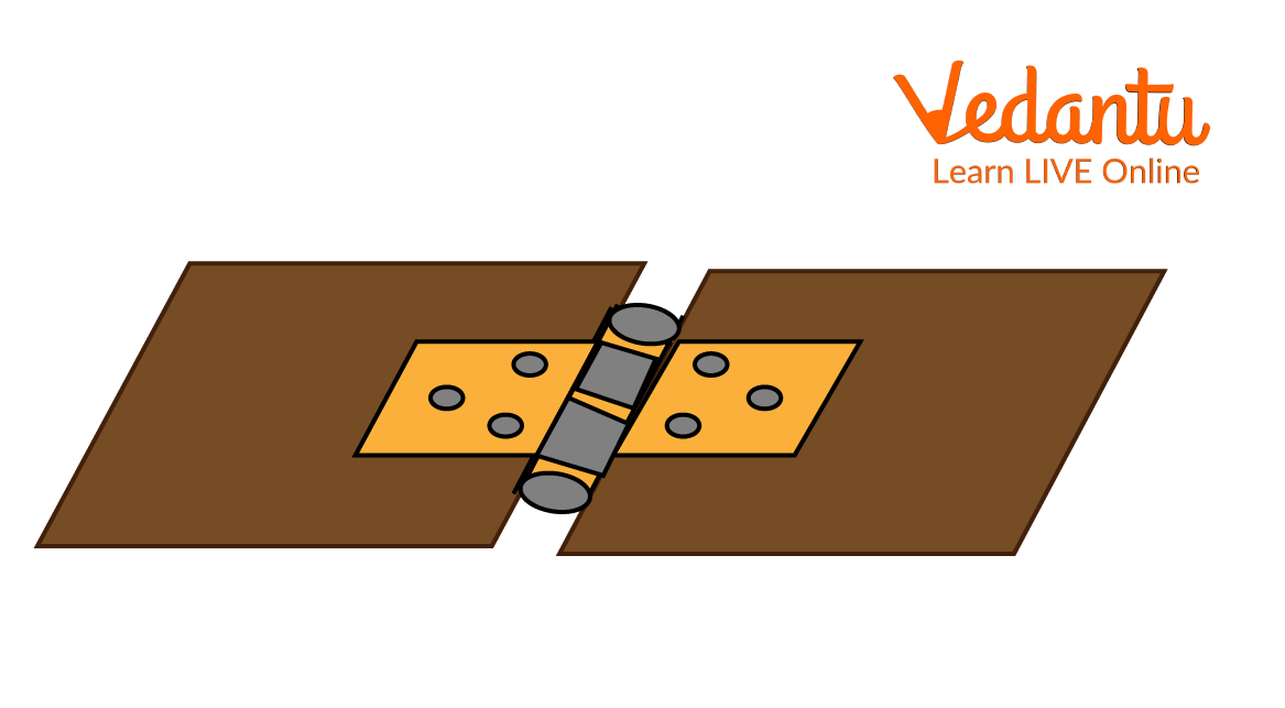
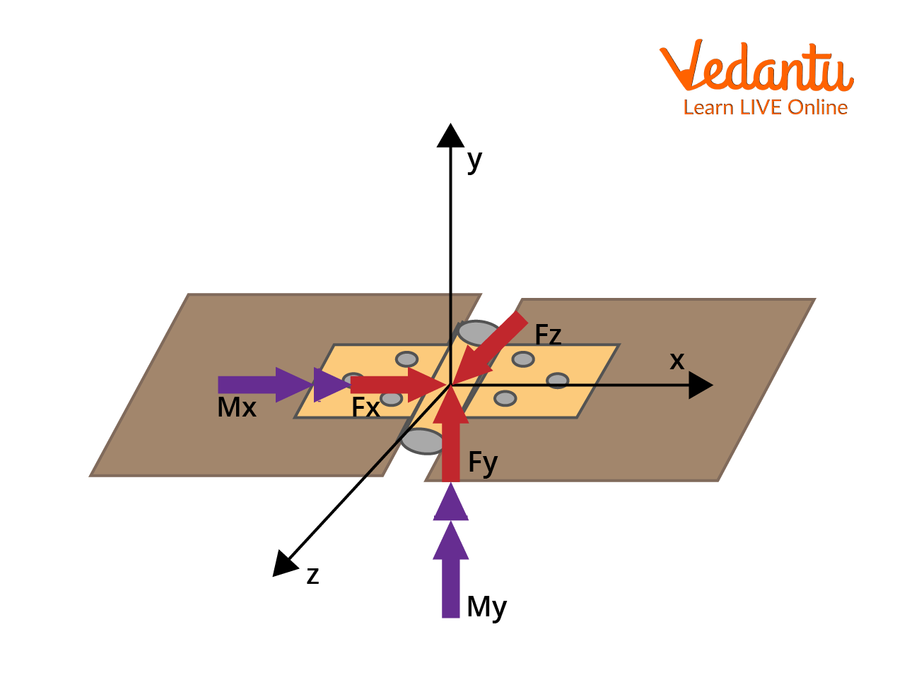
A hinge force is the net force exerted by a hinge on a body attached to it. The hinge itself provides a constraint, allowing rotation about a fixed axis but restricting translational motion at the joint. This force generally has two perpendicular components acting in the plane of the hinge mechanism, and can have a third component if the system is three-dimensional.
In mechanical systems, the hinge force maintains the physical connection and enables desired rotational or oscillatory motion. It arises as a reaction force that enforces the boundary conditions imposed by the hinge joint and is crucial in analyzing problems involving rods, frames, or doors attached to fixed or movable hinges.
Hinge Force in Free Body Diagrams
In free body diagrams, the hinge force is represented by its orthogonal components at the point of contact. Typically, for a two-dimensional mechanism, the force is resolved into horizontal and vertical components, often denoted as $N_1$ and $N_2$. The net hinge force is then obtained as the vector sum of these components, using the Pythagorean relation: $N = \sqrt{N_1^2 + N_2^2}$.
The proper construction of a free body diagram with correct hinge forces is essential for the correct application of conditions of equilibrium, including the analysis of torque and force balances. This is particularly important in problems involving rotational motion, as discussed in Circular Motion.
Derivation of Hinge Force: Worked Example
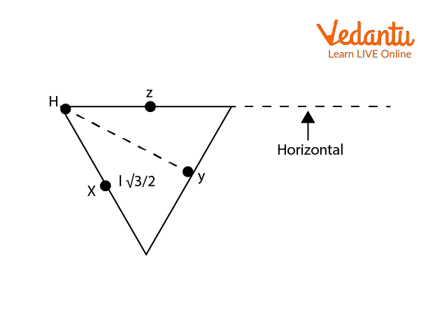
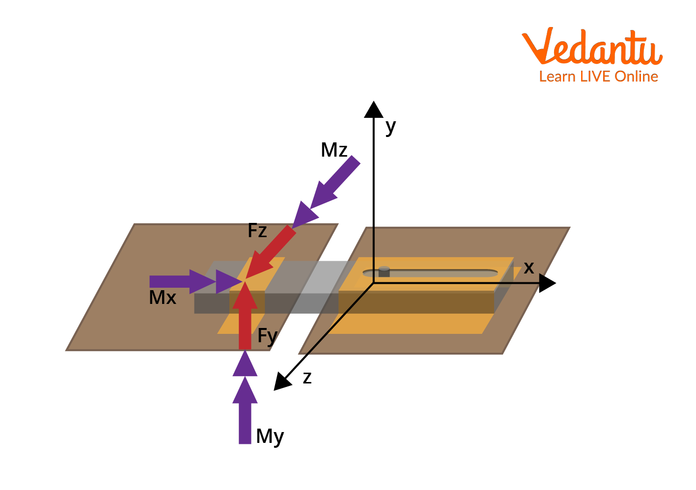
To illustrate the calculation of hinge force, consider a rigid isosceles triangle frame constructed of three uniform thin rods, each of mass $m$ and length $l$. The frame is allowed to rotate freely in a vertical plane about a hinge at one of its vertices, denoted H.
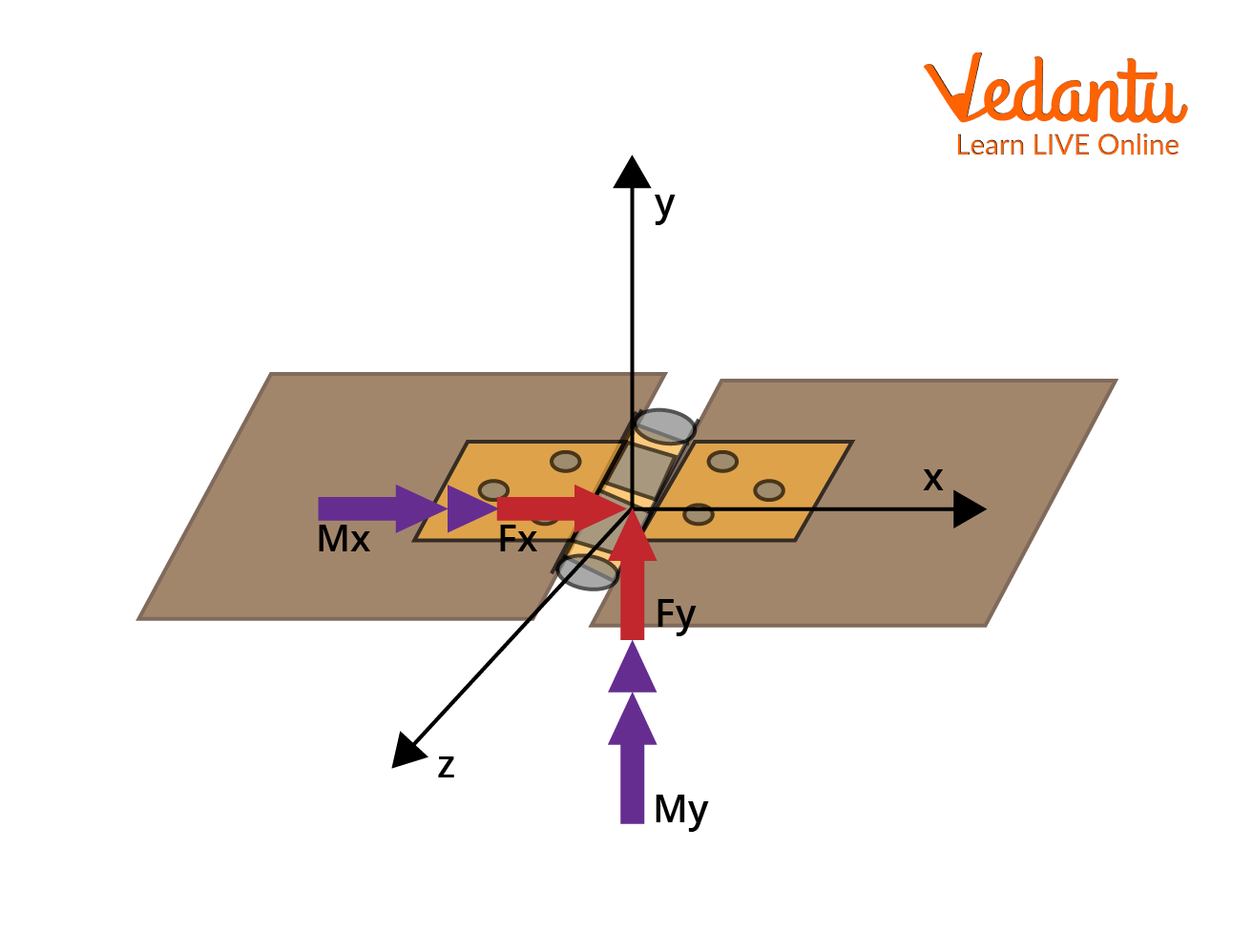
When the frame is released from rest, each rod applies a downward force equal to $mg$ at points $x$, $y$, and $z$. The torque about the hinge due to each rod can be calculated and summed to obtain the total torque.
The relevant moments are:
- About the x-axis: $M_x = \dfrac{1}{2} m g l$
- About the y-axis: $M_y = \dfrac{1}{2} m g l \sin 30^\circ$
- About the z-axis: $M_z = \dfrac{\sqrt{3}}{2} m g l \cos 30^\circ$
Summing up, total torque is:
$\tau_{\text{total}} = m g \left( \dfrac{1}{2} + \dfrac{1}{2} \sin 30^\circ + \dfrac{\sqrt{3}}{2} \cos 30^\circ \right) l$
On simplification using trigonometric values:
$\tau_{\text{total}} = m g l \left( \dfrac{1}{2} + \dfrac{1}{4} + \dfrac{3}{4} \right ) = m g l \left( \dfrac{3}{2} \right )$
The moment of inertia about the hinge is:
$I_{\text{total}} = I_{HA} + I_{HB} + I_{AB} = \dfrac{m l^2}{3} + \dfrac{m l^2}{3} + \dfrac{5 m l^2}{6} = \dfrac{3}{2} m l^2$
Equating torque to the moment of inertia times angular acceleration, the angular velocity $\omega$ at release is:
$\dfrac{3}{2} m g l = \dfrac{3}{2} m l^2 \omega \implies \omega = \dfrac{g}{l}$
The hinge force components are derived as:
- $N_1 = 3 m g \cos 60^\circ = \dfrac{3}{2} m g$
- $N_2 = \dfrac{\sqrt{3}}{2} m g$
Therefore, the magnitude of the hinge force is:
$N = \sqrt{N_1^2 + N_2^2} = \sqrt{ \left( \dfrac{3}{2} m g \right )^2 + \left( \dfrac{\sqrt{3}}{2} m g \right )^2 } = \sqrt{3} m g$
Hinge Reaction in Mechanical Systems
The hinge reaction refers to the resultant force and possible moment that the hinge exerts on a body. This is especially relevant in analyzing trap doors or beams resting on multiple supports. In general, a hinge can provide two unknown force components perpendicular to its axis and, in some cases, reaction moments depending on the support configuration.
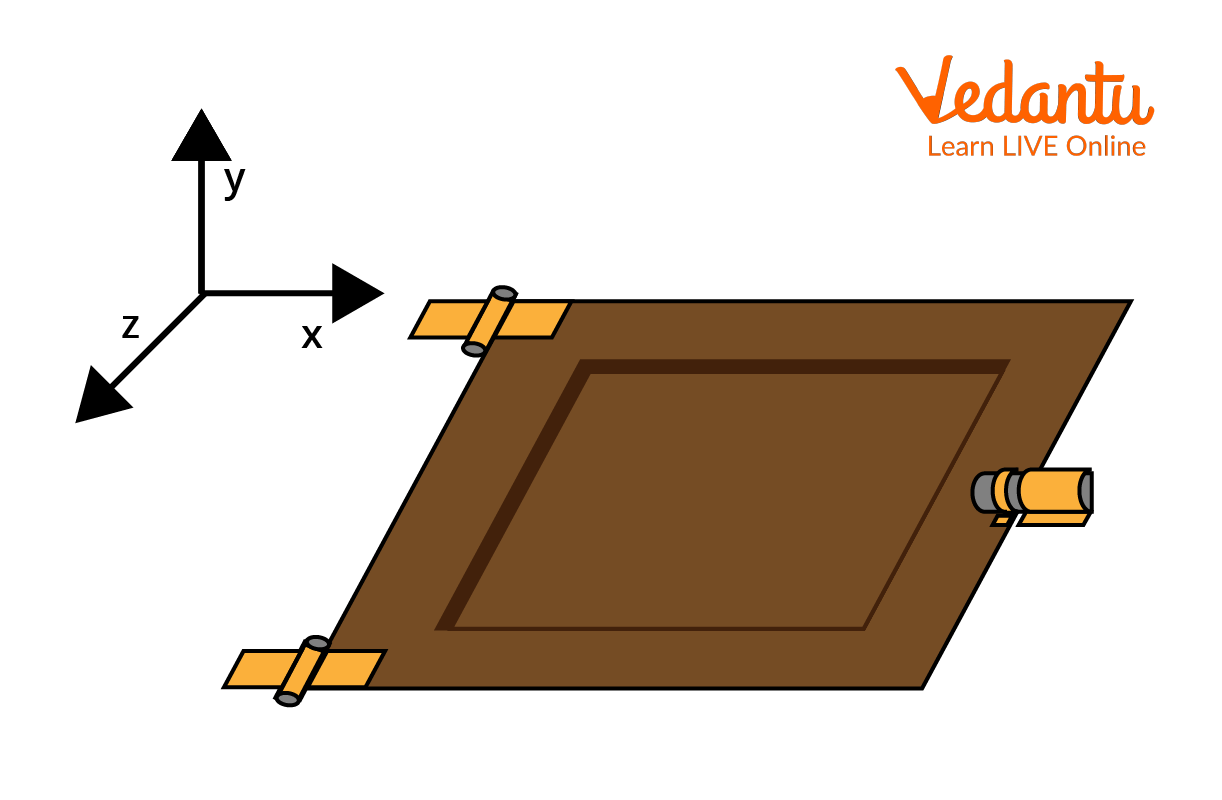
For a typical three-support system such as a trap door, the reactions at each support differ based on the nature of the bearing or hinge. The first support allows translation and rotation along certain axes, while standard hinges and bolts impose further restrictions on motion and may provide more complex reactions.
Accurate identification of reactions at various supports is crucial for solving problems involving static equilibrium and torque, for which knowledge of Torque is essential.
Direction of Hinge Force
The direction of hinge force is determined by equilibrium conditions for all forces and torques acting on the system. In a horizontal bar hinged at one end and subjected to external forces, the hinge force is opposite to the net force resulting from other applied forces at the free end, ensuring equilibrium.
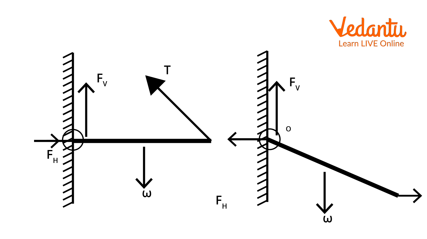
In cases involving multiple forces with horizontal and vertical components, the assumptions regarding the direction are verified by solving the equilibrium equations. If the calculated result is positive, the initial assumption about the direction is correct; a negative result indicates the opposite direction.
Importance in Statics and Dynamics
Understanding hinge forces is essential for solving mechanics problems in both statics and dynamics. The concept ensures the rigid body's motion constraints are satisfied and clarifies the interplay of external forces, moments, and internal reactions, especially when drawing free body diagrams. For further study, topics like Moment Of Inertia and Kinematics are closely related.
General Properties of Hinge Force
| Property | Description |
|---|---|
| Components | Horizontal and vertical; possibly axial |
| Direction | Opposes unbalanced forces or torques |
| Magnitude Calculation | Via equilibrium equations |
| Dependency | Affected by applied external forces |
Summary of Related Concepts
Hinge force analysis combines knowledge from rotational motion, torque, and equilibrium of rigid bodies. Mastery of hinge force is fundamental for topics involving mechanisms, levers, and supports. Concepts such as Static And Dynamic Friction and Circular And Rotational Motion further enhance understanding of mechanical frameworks involving hinges.


FAQs on Understanding Hinge Force in Physics
1. What is hinge force in physics?
Hinge force is the reaction force that the hinge exerts on a body attached to it to maintain equilibrium.
Key points:
- Acts at the hinge point of a body (like a door or rod attached to a wall)
- Consists of both vertical and horizontal components
- Keeps the object supported and balanced
- Always acts opposite to the force applied by the body on the hinge
- CBSE Physics syllabus covers reaction forces and equilibrium of rigid bodies
2. How do you calculate the hinge force in a beam attached to a wall?
The hinge force on a beam is calculated by resolving all forces and applying the equations of equilibrium.
- Draw a free-body diagram of the beam
- Mark all external forces and reactions at the hinge
- Use equilibrium conditions: ∑Fx = 0, ∑Fy = 0, and ∑M = 0
- Solve for horizontal (H) and vertical (V) components of hinge force
- The resultant hinge force, F = √(H² + V²)
3. Is hinge force the same as normal force?
No, hinge force and normal force are different types of reaction forces.
- Hinge force: Acts at the point of support provided by a hinge; has both horizontal and vertical components
- Normal force: Acts perpendicular to a surface at contact; only has a single (usually vertical) component
- Hinge force is more general, used in rotational and multi-dimensional scenarios
4. What are the components of hinge force?
The hinge force usually has two perpendicular components:
- Horizontal component (Fx) – parallel to the wall or support
- Vertical component (Fy) – perpendicular to the wall or support
5. Why does a hinge exert both horizontal and vertical forces?
A hinge must exert both horizontal and vertical forces to counteract all the forces and torques acting on the attached body.
- Ensures rotational and translational equilibrium
- Balances forces from gravity, applied loads, and reactions
- Maintains stationary position of the beam or rod
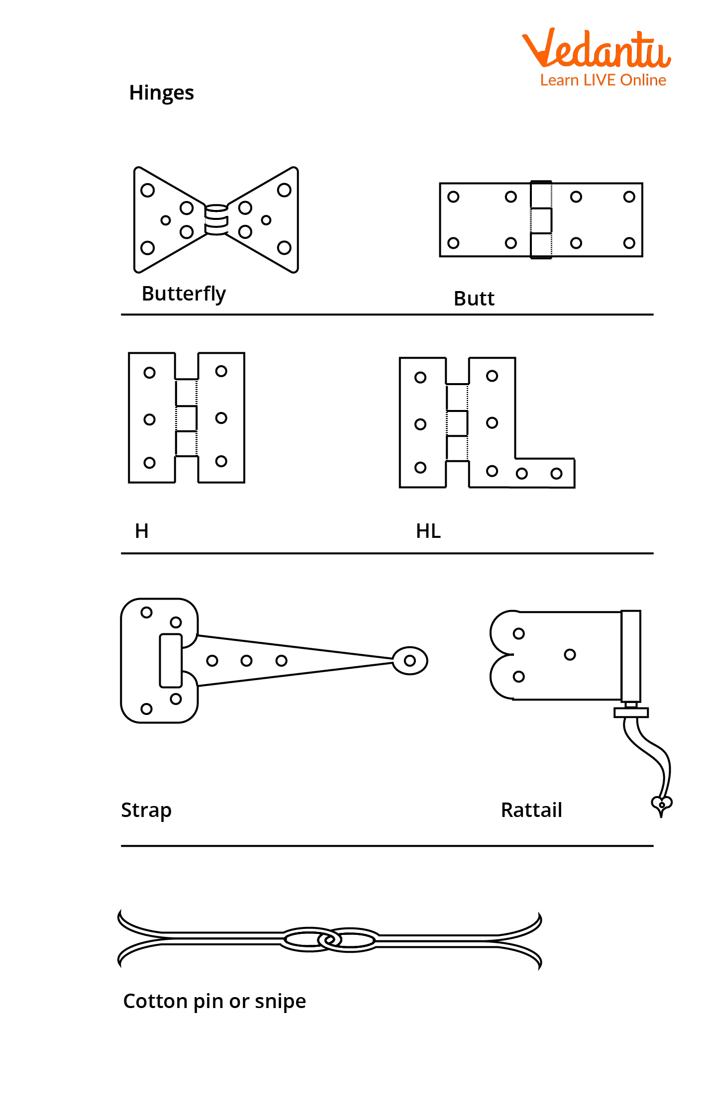
6. Where is hinge force used in daily life?
The concept of hinge force is used in several everyday items that rotate around a fixed point.
- Doors attached to walls
- Window frames
- Gymnastic rings and swing sets
- Flags mounted on poles
- Drawbridges and gates
7. How do you resolve hinge force into its components?
To resolve hinge force:
- Draw the force at the hinge as a vector
- Break it into two perpendicular components: horizontal (Fx) and vertical (Fy)
- Use equilibrium equations to find their values
- The resultant hinge force is calculated using Pythagoras' theorem: F = √(Fx² + Fy²)
8. What is the direction of hinge force in equilibrium?
In equilibrium, the hinge force acts in a direction and magnitude such that it balances other forces to keep the body stationary.
- Its exact direction depends on the applied forces and their points of action
- Always directed to restore balance and counter net force and torque
- Consists of horizontal and vertical components at right angles
9. Can hinge force be zero?
The hinge force is rarely zero because it provides essential support; it can only be zero if there is no force acting on the attached body, which is uncommon in practical scenarios.
- If the body is unsupported, hinge force is needed to prevent motion
- In theoretical cases with perfect balance and no external forces, it could approach zero
10. What happens if the hinge force is not enough to support a body?
If the hinge force is insufficient, the body may rotate, fall, or detach from the support.
- Loss of equilibrium and stability
- Potential structural failure or accident
- Highlighting the importance of correct calculation and design of hinges