


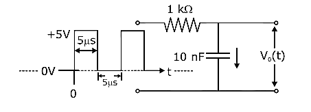
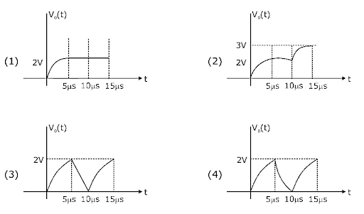
For the given input voltage waveform \[{V_{in}}(t)\], the output voltage waveform \[{V_o}\left( t \right)\], across the capacitor is correctly depicted by:
Answer
232.8k+ views
Hint:First of all we have to observe the given figure in the question, what type of the circuit is given and what are the major aspects that can be performing in the circuit. It is important to identify the type and the work of circuit in every question which is of this kind. Here we can see that the circuit is an RC circuit, and then we have to recall all the concepts related to RC circuits.
Formula used:
\[Q = {Q_0}\left( {1 - {e^{ - \dfrac{t}{{RC}}}}} \right)\]
\[V = {V_0}\left( {1 - {e^{ - \dfrac{t}{{RC}}}}} \right)\]
Complete step by step solution:
The given circuit in the above diagram is an RC circuit where, R represents resistor which is present only one in a circuit and C represents capacitor which is also only one present in the RC circuit.
Given data: Resistor \[R = 1K\Omega \], Capacitor \[C = 10nF\]
To find: Output voltage waveform from the given options.
As the circuit is RC circuit, the input voltage that is given to the circuit is \[{V_{in}} = + 5V\], we have to find out the time constant as we can see there voltage is the function of time and also the graphs in given options are in the form of \[V\left( t \right)\]v/s time t.
Therefore, the time constant is given by:
\[\tau = RC = 1k\Omega \times 10nF\]
\[\Rightarrow \tau = {10^3} \times 10 \times {10^{ - 9}}\]
\[\Rightarrow \tau = 10\mu s\]
As we can see in input voltage at time \[t = 0\] capacitor has voltage zero and after \[t = 5\mu s\] it becomes zero again. That means during those \[5\mu s\]the capacitor gets charged and after \[5\mu s\] it is again discharged.
During charging process charge on capacitor is given by
\[Q = {Q_0}\left( {1 - {e^{ - \dfrac{t}{{RC}}}}} \right)\]
And voltage is given by
\[V = {V_0}\left( {1 - {e^{ - \dfrac{t}{{RC}}}}} \right)\] \[ \Rightarrow V = 5\left( {1 - {e^{ - \dfrac{5}{{10}}}}} \right)\] \[ \Rightarrow V = 5\left( {1 - {e^{ - \dfrac{1}{2}}}} \right)\]
\[ \Rightarrow V = 5\left( {\dfrac{{\sqrt e - 1}}{{\sqrt e }}} \right)\]
\[\therefore V = 1.96V\]
So, according to this all the above options are correct as we have calculated voltage here.
Now, during discharging charge on the capacitor is given by
\[Q = {Q_0}\left( {{e^{ - \dfrac{t}{{RC}}}}} \right)\]
Voltage is given by
\[V = {V_0}\left( {{e^{ - \dfrac{t}{{RC}}}}} \right)\]
\[ \Rightarrow V = 1.96\left( {{e^{ - \dfrac{1}{2}}}} \right) = 1.21V\]
Now, here we can see that while charging all the above options are correct but after further calculations we can see that during discharging minimum voltage reached is \[1.21V\] not zero thus \[\left( 3 \right)\] and \[\left( 4 \right)\]are incorrect then option \[\left( 1 \right)\]is also incorrect as it does not discharging and showing constant.
Therefore, the correct option is option \[\left( 2 \right)\].
Note: While solving this question we have to recall all the concepts related to the RC circuit. The most important part is charging and discharging the capacitor since only then can we answer correctly if we pay attention to the graphical representation.
Recently Updated Pages
JEE Main 2023 April 6 Shift 1 Question Paper with Answer Key
JEE Main 2023 April 6 Shift 2 Question Paper with Answer Key
JEE Main 2023 (January 31 Evening Shift) Question Paper with Solutions [PDF]
JEE Main 2023 January 30 Shift 2 Question Paper with Answer Key
JEE Main 2023 January 25 Shift 1 Question Paper with Answer Key
JEE Main 2023 January 24 Shift 2 Question Paper with Answer Key
Trending doubts
JEE Main 2026: Session 2 Registration Open, City Intimation Slip, Exam Dates, Syllabus & Eligibility
JEE Main 2026 Application Login: Direct Link, Registration, Form Fill, and Steps
Understanding the Angle of Deviation in a Prism
Hybridisation in Chemistry – Concept, Types & Applications
How to Convert a Galvanometer into an Ammeter or Voltmeter
Understanding Uniform Acceleration in Physics
Other Pages
JEE Advanced Marks vs Ranks 2025: Understanding Category-wise Qualifying Marks and Previous Year Cut-offs
Dual Nature of Radiation and Matter Class 12 Physics Chapter 11 CBSE Notes - 2025-26
Understanding the Electric Field of a Uniformly Charged Ring
JEE Advanced Weightage 2025 Chapter-Wise for Physics, Maths and Chemistry
Derivation of Equation of Trajectory Explained for Students
Understanding Electromagnetic Waves and Their Importance