


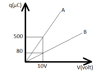
Figure shows charge (q) versus voltage (V) graph from series and parallel combination of two given capacitors. Determine the capacitances.
(A) $50\mu F$ and $30/muF$
(B) $20\mu F$ and $30/muF$
(C) $60\mu F$ and $40/muF$
(D) $40\mu F$ and $10/muF$
Answer
265.2k+ views
Hint In the figure a charge (q) versus voltage (V) graph from series and parallel combination of two capacitors is given. In order to find out the value of the two capacitors, we must use the formula $q = cV$, where q is the charge of the capacitor, V potential difference across two plates and c is the capacitance.
Complete step by step answer
We know that the charge q stored on either plate of a capacitor is directly proportional to the potential difference V across two plates, $q = cV$ where q is charge of the capacitor, V potential difference across two plates and c is the capacitance.
Here the slope of the graph will give capacitance. Now we have to determine capacitance for series and parallel combination.
In series combination,
$\dfrac{{{C_1}{C_2}}}{{{C_1} + {C_2}}} = \dfrac{q}{V}$
$ \Rightarrow \dfrac{{{C_1}{C_2}}}{{{C_1} + {C_2}}} = \dfrac{{80}}{{10}}$
$ \Rightarrow \dfrac{{{C_1}{C_2}}}{{{C_1} + {C_2}}} = 8 \times {10^{ - 6}}F$……. (i)
In parallel combination,
${C_1} + {C_2} = \dfrac{q}{V}$
$ = \dfrac{{500}}{{10}}$
$ = 50 \times {10^{ - 6}}F$
Putting the value of ${C_1} + {C_2}$ in equation (i) we get ${C_1}{C_2} = 400 \times {10^{ - 6}}F$
Therefore, capacitance in parallel should be 50/muF & capacitance in series must be 8μF.
It is only possible when ${C_1} = 10\mu F$ and ${C_2} = 40\mu F$
hence option D is correct.
Additional Information $q = cV$, here c is a constant of proportionality called the capacitance of the capacitor. The SI unit of capacitance is farad. 1 Farad = 1 coulomb/volt. The capacitance of a capacitor depends upon the area of the plates, the distance between the plates and the medium between them.
Note Whenever these types of questions appear, first thoroughly examine the graph. From the graph it can be easily determined that the slope of the graph gives capacitance as X and Y-axis represent voltage and charge respectively. Then determine the capacitance for series and parallel combination separately.
Recently Updated Pages
JEE Main 2025-26 Experimental Skills Mock Test – Free Practice
JEE Main 2025-26 Electronic Devices Mock Test: Free Practice Online
JEE Main 2025-26 Mock Tests: Free Practice Papers & Solutions
JEE Main 2025-26: Magnetic Effects of Current & Magnetism Mock Test
JEE Main 2025-26 Atoms and Nuclei Mock Test – Free Practice Online
JEE Main Mock Test 2025-26: Experimental Skills Chapter Online Practice
Trending doubts
JEE Main 2026: Exam Dates, Session 2 Updates, City Slip, Admit Card & Latest News
JEE Main Participating Colleges 2026 - A Complete List of Top Colleges
Kinematics Mock Test for JEE Main 2025-26: Practice & Ace the Exam
Kinematics Mock Test for JEE Main 2025-26: Comprehensive Practice
Hybridisation in Chemistry – Concept, Types & Applications
Understanding the Electric Field of a Uniformly Charged Ring
Other Pages
CBSE Class 12 Physics Question Paper 2026: Download SET-wise PDF with Answer Key & Analysis
JEE Advanced 2026 Notification Out with Exam Date, Registration (Extended), Syllabus and More
JEE Advanced Percentile vs Marks 2026: JEE Main Cutoff, AIR & IIT Admission Guide
JEE Advanced Weightage Chapter Wise 2026 for Physics, Chemistry, and Mathematics
JEE Advanced Marks vs Rank 2025 - Predict Your IIT Rank Based on Score
Derivation of Equation of Trajectory Explained for Students