


A current $i$ flows in a circular coil of radius $r$. If the coil is placed in a uniform magnetic field $B$ with its plane parallel to the field, magnitude of the torque that acts on the coil is
A. Zero
B. $2\pi iB$
C. $\pi r^{2}iB$
D. $2\pi r^{2}iB$
Answer
233.1k+ views
Hint:We have been asked to find the torque on a specific coil. The magnetic field of the coil has been given to us. Torque is a vector quantity, as we are aware. As a result, it possesses both direction and magnitude. We will apply the torque on a coil formula since we are just requested to compute the magnitude. in which the magnetic field and magnetic moments are discussed.
Formula used:
Magnetite of torque is the sign product of magnetic moment and magnetic field. Moment of inertia is the depend on current carried by coil (I) and on area of coil (A) such as
\[\tau =M\times B\]
$\tau =IAB\sin \theta $
Where, I is current carried by coil, A is area of coil ($\pi {{r}^{2}}$) B is magnetic field and sin component because coil and magnetic field are perpendicular to each other.
Complete step by step solution:
Now let's think about the scenario in which the magnetic field B is located in the same plane as the rectangular loop. The arms of the loop that are parallel to the magnets receive no force from the field, whereas the arms that are perpendicular to the magnets experience a force provided by \[{{F}_{1}}\].
${{F}_{1}}=IbB$
The plane is the target of this force.
The expression for a force \[{{F}_{2}}\]acting on the arm CD can be expressed similarly.
${{F}_{2}}=IbB={{F}_{1}}$
As can be seen, there is no net force acting on the loop, and the torque acting on the loop is given by,
$\tau ={{F}_{1}}\dfrac{a}{2}+{{F}_{2}}\dfrac{a}{2}$
$\Rightarrow \tau =IbB\dfrac{a}{2}+IbB\dfrac{a}{2}=I(ab)B=IAB$
where ab is the rectangle's area. Here, the torque has a tendency to cause the loop to revolve counterclockwise.
Consider the scenario where the loop's plane is not parallel to the magnetic field. Let's represent the angle between the field and the coil's normal. It is clear that the forces acting on the arms BC and DA will always be equal in strength and will act in opposition to one another. These forces cancel out each other's effects to produce zero-force or torque because they are equal opposites and collinear at all places. \[{{F}_{1}}\]and \[{{F}_{2}}\]provide the forces acting on the arms AB and CD. These forces, which can be generated by, are equivalent in strength and move in the opposite direction.
${{F}_{1}}={{F}_{2}}=IbB$
These forces work as a couple since they are not collinear, giving the coil a torque. The magnitude of the torque can be calculated by,
$\tau ={{F}_{1}}\dfrac{a}{2}\sin \theta +{{F}_{2}}\dfrac{a}{2}\sin \theta $
$\Rightarrow \tau =IabB\sin \theta $
$\Rightarrow \tau =IAB\sin \theta $
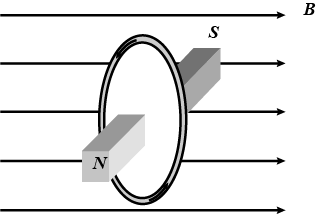
The presented circumstance is comparable to a bar magnet being positioned perpendicularly in a uniform magnetic field, as depicted in the following image. So torque on it $\tau =MB\sin {{90}^{0}}=(i\pi {{r}^{2}})B$
Note: A magnetic field is produced in a current-carrying coil. This magnetic field causes a torque to be applied to the coil, which is calculated as the product of the coil's number of turns, current through it, area of the loop, and magnetic field. The cross product of the magnetic moment vector and the magnetic field vector can be used to determine the torque's direction.
Formula used:
Magnetite of torque is the sign product of magnetic moment and magnetic field. Moment of inertia is the depend on current carried by coil (I) and on area of coil (A) such as
\[\tau =M\times B\]
$\tau =IAB\sin \theta $
Where, I is current carried by coil, A is area of coil ($\pi {{r}^{2}}$) B is magnetic field and sin component because coil and magnetic field are perpendicular to each other.
Complete step by step solution:
Now let's think about the scenario in which the magnetic field B is located in the same plane as the rectangular loop. The arms of the loop that are parallel to the magnets receive no force from the field, whereas the arms that are perpendicular to the magnets experience a force provided by \[{{F}_{1}}\].
${{F}_{1}}=IbB$
The plane is the target of this force.
The expression for a force \[{{F}_{2}}\]acting on the arm CD can be expressed similarly.
${{F}_{2}}=IbB={{F}_{1}}$
As can be seen, there is no net force acting on the loop, and the torque acting on the loop is given by,
$\tau ={{F}_{1}}\dfrac{a}{2}+{{F}_{2}}\dfrac{a}{2}$
$\Rightarrow \tau =IbB\dfrac{a}{2}+IbB\dfrac{a}{2}=I(ab)B=IAB$
where ab is the rectangle's area. Here, the torque has a tendency to cause the loop to revolve counterclockwise.
Consider the scenario where the loop's plane is not parallel to the magnetic field. Let's represent the angle between the field and the coil's normal. It is clear that the forces acting on the arms BC and DA will always be equal in strength and will act in opposition to one another. These forces cancel out each other's effects to produce zero-force or torque because they are equal opposites and collinear at all places. \[{{F}_{1}}\]and \[{{F}_{2}}\]provide the forces acting on the arms AB and CD. These forces, which can be generated by, are equivalent in strength and move in the opposite direction.
${{F}_{1}}={{F}_{2}}=IbB$
These forces work as a couple since they are not collinear, giving the coil a torque. The magnitude of the torque can be calculated by,
$\tau ={{F}_{1}}\dfrac{a}{2}\sin \theta +{{F}_{2}}\dfrac{a}{2}\sin \theta $
$\Rightarrow \tau =IabB\sin \theta $
$\Rightarrow \tau =IAB\sin \theta $
The presented circumstance is comparable to a bar magnet being positioned perpendicularly in a uniform magnetic field, as depicted in the following image. So torque on it $\tau =MB\sin {{90}^{0}}=(i\pi {{r}^{2}})B$
Note: A magnetic field is produced in a current-carrying coil. This magnetic field causes a torque to be applied to the coil, which is calculated as the product of the coil's number of turns, current through it, area of the loop, and magnetic field. The cross product of the magnetic moment vector and the magnetic field vector can be used to determine the torque's direction.
Recently Updated Pages
JEE Main 2023 April 6 Shift 1 Question Paper with Answer Key
JEE Main 2023 April 6 Shift 2 Question Paper with Answer Key
JEE Main 2023 (January 31 Evening Shift) Question Paper with Solutions [PDF]
JEE Main 2023 January 30 Shift 2 Question Paper with Answer Key
JEE Main 2023 January 25 Shift 1 Question Paper with Answer Key
JEE Main 2023 January 24 Shift 2 Question Paper with Answer Key
Trending doubts
JEE Main 2026: Session 2 Registration Open, City Intimation Slip, Exam Dates, Syllabus & Eligibility
JEE Main 2026 Application Login: Direct Link, Registration, Form Fill, and Steps
Understanding the Angle of Deviation in a Prism
Hybridisation in Chemistry – Concept, Types & Applications
How to Convert a Galvanometer into an Ammeter or Voltmeter
Understanding Uniform Acceleration in Physics
Other Pages
JEE Advanced Marks vs Ranks 2025: Understanding Category-wise Qualifying Marks and Previous Year Cut-offs
Dual Nature of Radiation and Matter Class 12 Physics Chapter 11 CBSE Notes - 2025-26
Understanding the Electric Field of a Uniformly Charged Ring
JEE Advanced Weightage 2025 Chapter-Wise for Physics, Maths and Chemistry
Derivation of Equation of Trajectory Explained for Students
Understanding Electromagnetic Waves and Their Importance