


All About Optics JEE Advanced Notes - Free PDF Download
Light
Light is a type of energy that causes our eyes to experience visual sensations.
Light is a type of electromagnetic wave that travels in a transverse direction.
The speed of light in vacuum is $3 \times 10^{8} \mathrm{~m} / \mathrm{s}$.
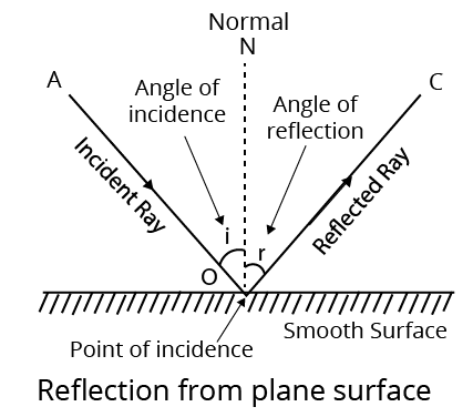
Reflection of Light
Reflection of light is the phenomenon of light rays bouncing back in the same medium after striking a smooth surface.
Reflection
There are Two Types of Reflection
Regular Reflection: when light reflects off a very smooth surface and forms a clear image, this is referred to as regular reflection.
Irregular Reflection: when a parallel light ray beam strikes a rough surface, the reflected rays scatter in various directions. This is referred to as irregular or diffuse reflection. Diffuse reflection refers to reflection from a rough surface.
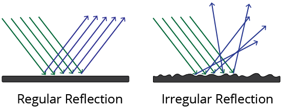
Different Types of Reflection
Laws of Reflection
There are Two Laws of Reflection
The angle of incidence and reflection are always equal.
$\angle i=\angle r$
At the point of incidence, the incident ray, reflected ray, and normal are all lie in the same plane.
Mirror
A mirror is a polished glass surface onto which almost all light is reflected. The mirror is called a plane mirror if the reflecting surface is plane, and a spherical mirror if the reflecting surface is spherical.
Image
Image is an optical appearance produced when light rays coming from an object are reflected or refracted from a mirror ( or appearing to meet ).
There are Two Types of Image
Real Image: When light rays from one point meet at another point after reflection, the image formed is known as a real image.
Virtual Image: The image formed is called a virtual image if the light rays coming from a point do not actually meet after reflection or appear to come from another point.
Reflection From Plane Mirror
The size of the image in a plane mirror is always equal to the size of the object, and it is virtual.
In a plane mirror, the image appears to be as far behind the mirror as the object in front of it.
Important Points Related to Simple Mirror are Given Below
When an object moves a distance towards or away from a mirror, its image moves a distance towards or away from the mirror.
The minimum mirror size required to see the full image of an observer is half the observer's height.
When the plane mirror is rotated in the plane of incidence by an angle $\theta$, then the reflected ray rotates by an angle $2 \theta .$
The focal length of a plane mirror is infinite, implying that its power is nil. The plane mirror produces a linear magnification of 1.
If two plane mirrors are kept facing each other at an angle $\theta$ and an object is placed between them, then number of images, $n=\dfrac{360^{\circ}}{\theta}-1$, if $\dfrac{360^{\circ}}{\theta}$ is even or the object lies symmetrically. Number of images, $n=\left(\dfrac{360^{\circ}}{\theta}\right)$, if $\dfrac{360^{\circ}}{\theta}$ is odd or the object lies asymmetrically.
There are an infinite number of images when two plane mirrors are parallel to each other.
The plane mirror is used in kaleidoscopes, periscopes, and looking glasses, among other things.
Spherical Mirror
The mirror is referred to as a spherical mirror if the reflecting surface is curved inwards or outwards.
Spherical Mirrors are of Two Types
Concave Mirror: Concave mirrors are spherical mirrors with an inwardly curved reflecting surface. Because a beam of light converges after reflection from its surface, it is also known as a convergent mirror. e.g. A concave mirror can be thought of as the inner curved surface of a shining spoon.
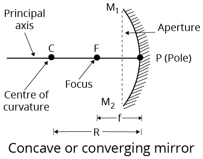
Concave Mirror
Convex Mirror: Convex mirrors are spherical mirrors with an outwardly curved reflecting surface. Because a beam of light diverges after reflection from its surface, it is also known as a divergent mirror. e.g. A shining spoon's outer curved surface can be treated or thought of as a convex mirror.
Some Definitions Related to Spherical Mirrors
Centre of Curvature: The centre of curvature of a spherical mirror is the centre of the sphere from which it is separated. In the above figures, it is marked by $C$.
Radius of Curvature: A spherical mirror's radius of curvature is the radius of the sphere from which the mirror is separated. In the above figure, it is shown by $R$.
Pole: The spherical mirror's pole is the midpoint of its reflecting surface. In the figure, it is shown by $P$.
Principal Axis: The line connecting the pole and the centre of curvature is the principal axis of a spherical mirror. In the figure, PC is the principal axis.
Aperture of Mirror: The aperture of a mirror refers to the portion of the reflecting surface that can be exposed to incident light.
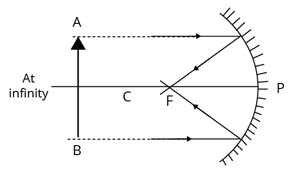
Principal Focus or Focus: After reflection, the light rays coming parallel to the principal axis actually meet or appear to be coming from this point on the principal axis of the mirror. It is represented by $F$. The focus of a concave mirror is in front of the mirror, whereas the focus of a convex mirror is behind the mirror. A concave mirror's focus is real, whereas a convex mirror's focus is virtual.
Focal Length: The focal length of a spherical mirror is the distance between the pole and the focus. It is represented by $f$.
(i) Plane mirrors have an infinite focal length.
(ii) The curvature radius of a plane mirror is infinite.
Relation Between Focal Length and Radius of Curvature of Spherical Mirror
When the aperture of the mirror is small, then the following relation is given below between focal length $(f)$ and radius of curvature$(R)$. i.e. $f=\dfrac{R}{2}$
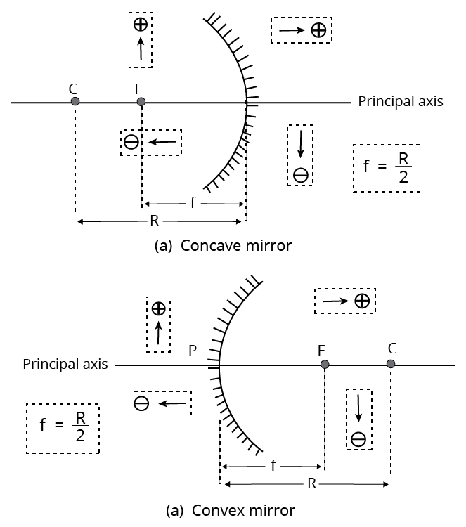
Sign Convention for Reflection by Spherical Mirrors
We will use a set of sign conventions called the new Cartesian sign convention based on Cartesian coordinates when dealing with light reflection by spherical mirrors.
The mirror's pole (P) is used as the origin in this convention. The X-axis of the coordinate system is taken as the principal axis of the mirror.
Sign Convention for Reflection by Spherical Mirrors
The Conventions are as Follows
Always place the object to the left of the mirror.
The pole of the mirror is used to measure all distances parallel to the principal axis (X-axis).
Negative distances to the left of the pole (-ve X-axis). Positive distances are those to the right of the pole (+ve X-axis).
Positive distances are those measured perpendicularly above the principal axis (along the +Y-axis).
Negative distances are those measured perpendicularly below the principal axis (along the -Y-axis).
Image Formation by Spherical Mirrors
There are two types of image formation by spherical mirrors.
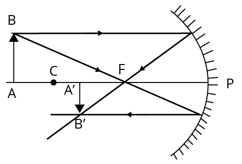
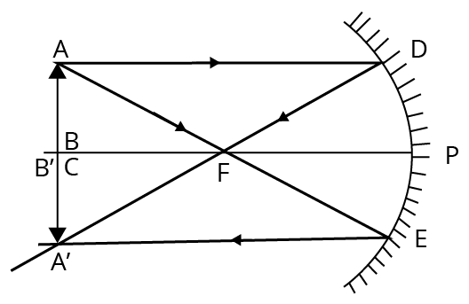
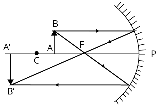
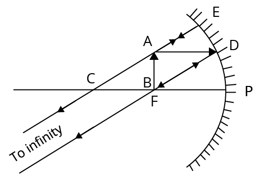
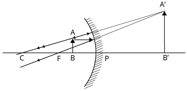
Image Formation by a Concave Mirror
The ray diagram, as well as the position and nature of the image formed by a concave mirror, is shown in the table below for various positions of the object.
Formation of Image by Concave Mirror for Different Positions of Object
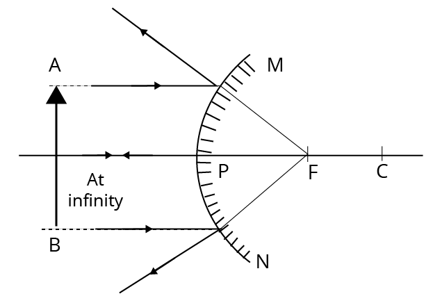
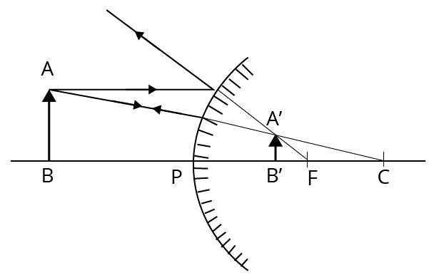
(ii) Image Formation by a Convex Mirror
There are two positions of the object that are considered when studying the image formed by a convex mirror. The first is when the object is infinitely far away from the mirror, and the second is when the object is finitely far away from the mirror.
The ray diagrams, as well as the position and nature of the image, are shown in the table below.
For the above two positions of the object, a convex mirror was used.
Formation of Image by Convex:
Mirror for Different Positions of Object
Mirror Formula
In a spherical mirror, the object distance $(u)$ is the distance between the object and its pole. The image distance $(v)$ is the distance between the image and the mirror's pole. We know that the relation between quantities $(u, v$ and $f)$, i.e. mirror formula, $\dfrac{1}{v}+\dfrac{1}{u}=\dfrac{1}{f}$
Here, u, v and $f$ are to be used according to their new Cartesian sign convention.
Linear Magnification
Linear magnification is defined as the ratio of image height to object height. It is represented by $(m)$.
i.e. $m=\dfrac{\text { height of image }(I)}{\text { height of object }(O)}$
Or Linear magnification is the ratio of image distance to object distance.$\text{ i}\text{.e}\text{. }m=\dfrac{\text{ image distance }(v)}{\text{ object distance }(u)}=\dfrac{-v}{u}$
The plane mirror produces a linear magnification of 1.
Identification of Mirrors
The nature of the mirror can be determined by observing the image produced by it at various positions of the object.
The mirror is called a plane mirror if the image formed by it is the same size as the object at different positions.
When the image formed by a mirror is diminished for all object positions, the mirror is said to be convex.
A concave mirror is one in which the image formed behind the mirror is longer than the object.
Refraction of Light
Refraction of light is the change in the path of a light ray as it travels from one medium to another.
If light travels from a rarer medium to a denser one, it bends towards the normal $(i>r)$ and when it travels from a denser medium to a rarer one, it bends away from the normal $(i<r)$.
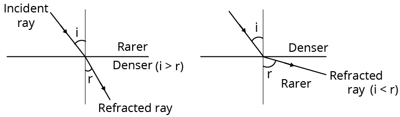
Refraction of Light
Here , $i=$ angle of incidence And $r=$ angle of refraction
The optically rarer medium is one in which the speed of light is greater, while the optically denser medium is one in which the speed of light is lower.
When a ray of light is refracted, its velocity and wavelength change, but the frequency remains constant.
i.e. $n_{1}=n_{2} $ or $\dfrac{v_{1}}{\lambda_{1}}=\dfrac{v_{2}}{\lambda_{2}}$
Laws of Refraction
The following laws govern the laws of refraction.
(i) At the point of incidence, the incident ray, the normal to the surface of separation, and the refracted ray all lie in the same plane.
(ii) The ratio of sine of angle of incidence to the sine of angle of refraction is constant for light rays of the same color passing through two medium, i.e. $\dfrac{\sin i}{\sin r}={ }_{1} \mu_{2}=\dfrac{\mu_{2}}{\mu_{1}} \text { [constant] }$ for same pair of media.
Here, ${ }_{1} \mu_{2}$ is called the refractive index of the second medium with respect to the first medium. This law is known as Snell's law.
Refractive Index
Refractive index of a medium,$\mu=\dfrac{c}{v}=\dfrac{\lambda_{\text {air }}}{\lambda_{\text {medium }}}=\dfrac{\text { speed of light in vacuum }}{\text { speed of light in the medium }}$
Here, $c$=speed of light in vacuum $=3 \times 10^{8} \mathrm{~m} / \mathrm{s}$
The refractive index of two mediums is determined by the nature of the two mediums, the colour of the light ray, and the temperature of the two mediums.
The refractive index of a medium decreases as its temperature rises.
The optical property of a medium is its refractive index.
All mediums' refractive indices are measured in relation to air.
Diamonds have the highest refractive index.
If a light ray travels from vacuum to a medium, the absolute refractive index of that medium is called refractive index.
${ }_{1} \mu_{2}$ $=\dfrac{\text { velocity of light in first medium }}{\text { velocity of light in second medium }}$
${ }_{1} \mu_{2}$ $=\dfrac{\text { wavelength }(\lambda) \text { in first medium }}{\text { wavelength }(\lambda) \text { in second medium }}$
Note For glass/water pair, ${{\mu }_{g}}=\dfrac{_{a}{{\mu }_{g}}}{_{a}{{\mu }_{w}}}$.
Refraction Through a Rectangular Glass Slab
When a light ray passes through a glass slab, the emergent ray is parallel to the incident ray but slightly offset to the side.
Refraction occurs twice in this case, once when the ray enters the glass slab from the air and again when it exits the glass slab to the air.
The angle between the incident and emergent rays is perpendicular, $d=t\left[1-\dfrac{\cos i}{\sqrt{\mu^{2}-\sin ^{2} i}}\right] \sin i$
This value is equal to the lateral shift of the ray.
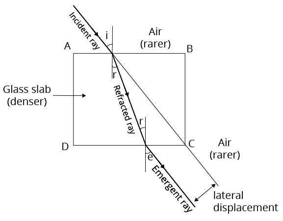
Refraction Through a Rectangular Glass Slab
Here, i = angle of incidence, $r=$ angle of refraction And $e=$ angle of emergence.
Critical Angle
When a light ray travels from a denser medium to a rarer medium, the angle of refraction increases as the angle of incidence increases, so the critical angle is the angle of incidence at which the angle of refraction equals 90 degree.
$\sin C=\dfrac{\mu_{R}}{\mu_{D}} \Rightarrow C=\sin ^{-1}\left(\dfrac{\mu_{R}}{\mu_{D}}\right)=\sin ^{-1}\left(\dfrac{1}{{ }_{r} \mu_{d}}\right)$
Total Internal Reflection
The ray is reflected back into the denser medium if the angle of incidence in the denser medium is greater than the critical angle (c).
This phenomenon is known as total internal reflection.
For total internal reflection, it is necessary that
From a denser medium, light rays should travel to a rarer medium.
In a denser medium, the angle of incidence should be greater than the critical angle.
Some Phenomena Based on Total Internal Reflection (TIR)
A diamond's brilliance is due to total internal reflection.
A fish can't see the entire surface from inside the water, it sees only a circular path of radius r of light. The expression of $r=\dfrac{h}{\sqrt{\mu^{2}-1}}$
The phenomenon of mirage occurs in the desert due to total internal reflection.
Due to total internal reflection, the air bubbles in glass paper weight appear silvery white.
Due to total internal reflection, a blackened test tube dipped in water from the outside appears silvery white.
As the temperature rises, so does the critical angle.
Refraction From Spherical Surfaces
There are two types of refraction at a spherical surface
Convex
Concave
The refraction formula for both surfaces is $\dfrac{_{1}{{\mu }_{2}}}{v}-\dfrac{1}{u}=\dfrac{_{1}{{\mu }_{2}}-1}{R}$
$\mu_{2}$ is the refractive index of the second medium with respect to the first. If $\mu_{1}$ and $\mu_{2}$ are refractive indices of first and second medium with respect to air, then $\dfrac{\mu_{2}}{v}-\dfrac{\mu_{1}}{u}=\dfrac{\mu_{2}-\mu_{1}}{R}$
Lens
A lens is a refracting medium piece that is bounded by two surfaces, at least one of which is curved. The most common lenses are spherical lenses, which have either both spherical surfaces or one spherical and one plane surface.
There are Two Types of Lenses:
Convex or Converging Lens
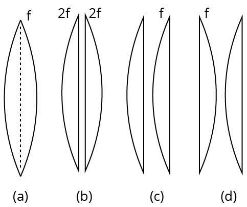
Convex lens is a transparent medium that is bound by two bulging surfaces. There are three types of convex lenses (as shown below)
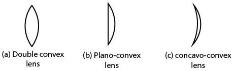
Convex or Converging Lens
When a plano-convex lens' plane surface is silver polished, it behaves like a concave mirror with a focal length half that of the initial value.
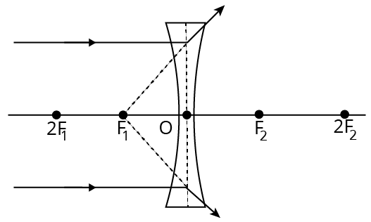
Concave or Divergent Lens
Concave lens is a transparent medium bounded by two hollow surfaces.
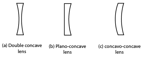
Concave or Divergent Lens
Some Definitions Related to Lenses
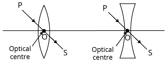
Optical Center: The optical centre of a lens is its central point. It is symbolised by the letter O. The optical centre is a point inside or outside the lens where incident rays refract without deviating from their path.
Principal focus Lens has two principal foci.
First Principal Focus: It's a point on the lens's principal axis where the rays that originate from or are directed to become parallel to the axis after refraction.
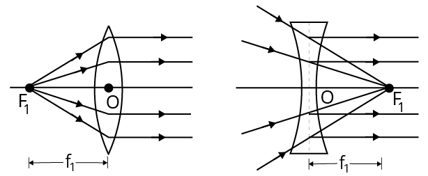
First Principal Focus
Second Principal Focus: After refraction from the lens, it is the point on the principal axis where rays coming parallel to the principal axis converge on the opposite side of the lens (convex) or appear to meet on the same side of the lens (concave).
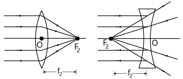
Second Principal Focus
Convex lenses have real foci, whereas concave lenses have virtual foci.
Centre of Curvature: The centres of curvature of the lens are the centres of the two imaginary spheres of which the lens is a part. With respect to its two curved surfaces, a lens has two centres of curvature.
Radii of Curvature: The radii of curvature of the lens are the radii of the two imaginary spheres of which the lens is a part. R is the symbol for it. A lens has two curvature radii. These could be equal or not.
Image Formation by Lenses
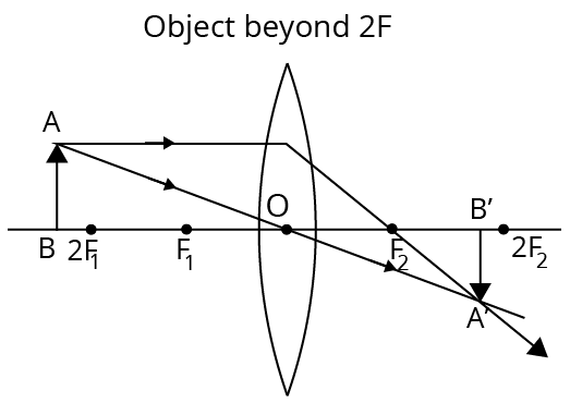
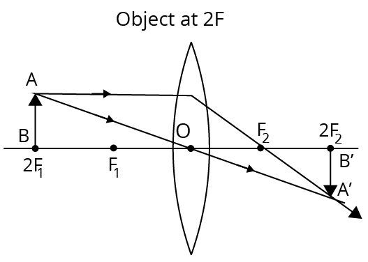
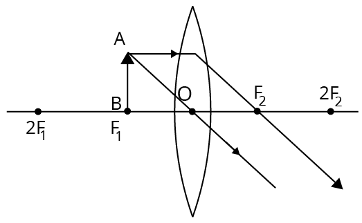
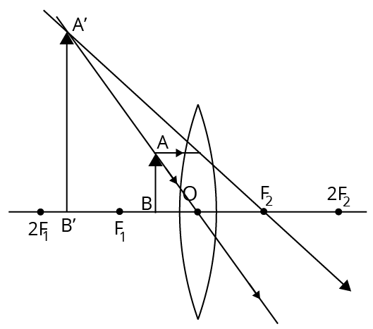
Formation of Image by a Convex Lens
The ray diagrams, as well as the position and nature of the image formed by a convex lens, are shown in the table below for various positions of the object.
Formation of Image by Convex Lens for Different Positions of Object
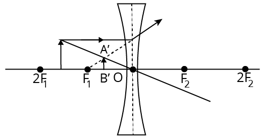
Formation of Image by a Concave Lens
There are two positions of objects for studying image formation by concave lens.
We always get erect images, diminished images, and virtual images when using a concave lens. If the object is very far away, the images formed by lenses will be greatly reduced.
The ray diagrams, as well as the position and nature of the image formed by the concave lens for the above two positions of the object, are shown in the table below.
Formation of Image by Concave Lens for Different Positions of Object
Important Formula Related to Lens
Lens Formula: For both convex and concave lenses, the formula connecting the object and image distance is $\dfrac{1}{f}=\dfrac{1}{v}-\dfrac{1}{u} .$ Here, f=focal length of lens, $u=$ Object distance and $v=$ image distance
Power of Lens: The power of a lens refers to its ability to converge or diverge light rays. The reciprocal of focal length is used to calculate it. Power, $\quad P=\dfrac{1}{f \text { (in metre) }} \Rightarrow P=\dfrac{100}{f \text { (in cm) }}$. Its unit is diopter (D). Power of a plane mirror is zero.
Newton's Formula for Lenses: The lens formula is given by Newton. $f^{2}=a_{1} a_{2} \quad \Rightarrow \quad f=\sqrt{a_{1} a_{2}}$ Here, $a_{1}=$ distance of object from first focus and $a_{2}=$ distance of object from second focus
Magnification Produced by Lens
The linear magnification of a lens is given by
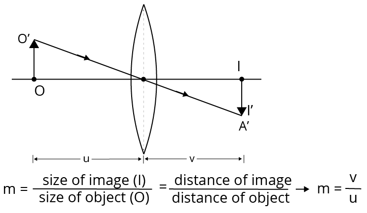
Linear Magnification
Areal magnification of lens Areal magnification $\left(m_{s}\right)$ is given by$m_{s}=\dfrac{\text { area of image }}{\text { area of object }}=\dfrac{A_{i}}{A_{o}}=m^{2}=\left(\dfrac{f}{f+u}\right)^{2}$
Relationship between object speed and image $v_{i}=\left(\dfrac{f}{f+u}\right) v_{a}$
Some Phenomenon Related to Lens
Lens Immersed in a Liquid If $_{a}{\mu }_{g}$ is the refractive index of lens and ${\mu}_l$ refractive index of liquid, then the total length of lens is $\dfrac{1}{f}=\left( _{l}{{\mu }_{g}}-1 \right)\left( \dfrac{1}{{{R}_{1}}}-\dfrac{1}{{{R}_{2}}} \right)$
Cutting of a Lens
If a focal length symmetrical convex lens is cut into two parts along its optical axis, each part (a plano-convex lens) has a focal length of 2 f. If the two parts are joined as shown in the figure, however, then the focal length of the combination is again $f$.
Cutting of a Lens
If a symmetrical convex lens with a focal length of f is divided into two parts along the principal axis, the focal length of each part remains constant at f. The focal length of the combination if these two parts are joined with curved ends on one side is $\dfrac{f}{2}$. But on joining two parts in opposite senses the net focal length becomes infinite (or net power $=0$ ).
Combination of Thin Lenses
If two or more lenses are in contact, the combination's equivalent focal length is
$\dfrac{1}{f}=\dfrac{1}{f_{1}}+\dfrac{1}{f_{2}}+\ldots=\sum_{i=1}^{n} \dfrac{1}{f_{i}}$
Power of combination,
$P=P_{1}+P_{2}+\ldots=\sum_{i=1}^{n} P_{i}$
If two lenses of focal lengths $f_1$ and $f_2$ are separated by a distance $x$, then its equivalent focal length,
$\dfrac{1}{F}=\dfrac{1}{f_{1}}+\dfrac{1}{f_{2}}-\dfrac{x}{f_{1} f_{2}}$
Power of combination,
$P=P_{1}+P_{2}-x P_{1} P_{2}$
Prism
A prism is a transparent refracting medium that is defined by two plane surfaces that are angled at an angle.
Angle of Deviation
The angle formed by the incident rays.
And emergent ray (e) is called angle of deviation $(\delta)$
Prism
Dispersion of Light
When white light strikes a glass prism, it splits into its seven colour components according to the VIBGYOR sequence.
Dispersion of white light is the term for this phenomenon.
Dispersion of Light
The refractive index of glass is highest for violet light and lowest for red light.
As a result, the violet colour of white light (sunlight) deviated the most, while the red colour deviated the least.
Angular Dispersion
It refers to the angle between the two extreme rays.
Angular dispersion, $\theta=\delta_{V}-\delta_{R}=\left(\mu_{V}-\mu_{R}\right) A$
Dispersive Power
The ratio of angular dispersion to the mean deviation suffered by a light beam is used to determine the dispersive power of a prism material.
Dispersive power, $\omega=\dfrac{\delta_{V}-\delta_{R}}{\delta}=\dfrac{\mu_{V}-\mu_{R}}{\mu-1}$ Here, $\mu$ Is the mean value of the refractive index of prism?
The dispersive power of a prism is determined solely by its material and is unaffected by the prism's angle, angle of incidence, or size.
Dispersive power is a non-dimensional and unitless term.
A flint glass prism has more dispersive power than a crown glass prism.
Dispersion without Deviation
(Direct Vision Prism)
To achieve dispersion without mean deviation, we combine two prisms made of different materials.
Direct Vision Prism
$A^{\prime}=\left(\dfrac{\mu-1}{\mu^{\prime}-1}\right) A$
Deviation without Dispersion (Achromatic Prism)
We use a combination of two prisms made of different materials to produce deviation without dispersion.
$A^{\prime}=\dfrac{\left[\mu_{V}-\mu_{R}\right]}{\left[\mu_{V}^{\prime}-\mu_{R}^{\prime}\right]} A$
Net dispersion caused $=\left(\mu_{V}-\mu_{R}\right) A+\left(\mu_{V}^{\prime}-\mu_{R}^{\prime}\right) A^{\prime}$ $=(\mu-1) A\left(\omega-\omega^{\prime}\right)=\delta\left(\omega-\omega^{\prime}\right)$
Resultant deviation produced $=\delta\left[1-\dfrac{\omega}{\omega^{\prime}}\right]$
Scattering of Light
When light passes through a medium in which particles of the order of the wavelength of light are suspended, light deviates in different directions when it strikes these particles.
Scattering of light is the term for this phenomenon. As a result, red light scatters the least (wavelength is highest) and violet light scatters the most (wavelength is least).
Danger signals are red in colour because red light scatters the least and can thus be seen from a long distance.
The sky appears blue because the blue colour of light scatters the most in sunlight, and this scattered blue light enters our eyes, causing the sky to appear blue.
Clouds appear white because they are made up of large water droplets and dust particles that scatter all light colours equally. White is the result of combining all seven colours of sunlight.
Because there is no atmosphere in space, no light scattering occurs, the sky appears black to astronauts from space.
Human Eye
One of the most important and sensitive sense organs in the human body is the eye.
It allows us to appreciate the beautiful world and colours that surround us.
It is made up of a lens made up of living tissues.
A Human Eye has the Following Main Parts
Cornea: It's the spherical transparent membrane that covers the front of the eye. This membrane allows light to enter the eye.
Crystalline Lens: A convex lens, similar to a jelly made of proteins, is made of a transparent, soft, and flexible material.
Iris: Between the cornea and the lens, there is a dark muscular diaphragm. It regulates the pupil's size.
Pupil: It is a small opening between the iris and the cornea that allows light to enter the eye.
Ciliary Muscles: They help to keep the lens in place and modify the curvature of the lens.
Retina: The image is formed on the light-sensitive surface of the eye. It is made up of rods and cones that are sensitive to light.
Optic Nerve: It connects the retina to the brain and transmits visual information.
Sclera: It's an opaque, fibrous, protective layer of the eye that's made up of collagen and elastic fibre. The white of the eye is another name for it.
Blind Spot: The optic nerve leaves the eye at this location. Because it lacks rods and cones, any image formed here is not sent to the brain.
Aqueous Humour: The aqueous humour is a transparent liquid that fills the space behind the cornea.
Vitreous Humour: Another liquid called vitreous humour fills the space between the eye lens and the retina.
Accommodation of Eye: It is the ability of the eye lens to change its focal length in order to form sharp images of objects at various distances from the eye on the retina.
Range of Vision: It is the distance between the eye's near and far points.For normal eye, the range of vision is 25cm to infinity.
Near Point: It is the distance between an object and the human eye at which a sharp image is formed on the retina.
Human Eye
Defects of Vision
Myopia or Short Sightedness: It is an eye defect that causes a person to be able to see nearby objects clearly but not far away objects. The far point of the eye shifts from infinity to a closer distance in this defect. A concave lens of appropriate power can be used to remove the flaw.
Hypermetropia or Long Sightedness: It is an eye defect that causes a person to be able to see far away objects clearly but not nearby objects.
Presbyopia: It is found in the elderly. This flaw makes it difficult to read comfortably and clearly. Bifocal lenses can be used to correct this flaw. The near point of the eye shifts away from the eye in this defect. A convex lens of appropriate power can be used to remove the flaw.
Astigmatism: A person with this defect is unable to focus on both horizontal and vertical lines at the same time. This flaw can be corrected with the use of suitable cylindrical lenses.
Colour Blindness: A person with this defect is unable to distinguish between a limited number of colours. The absence of cone cells sensitive to only a few colours is the cause of this defect. This flaw is irreversible.
Cataract: An opaque, white membrane forms on the cornea in this defect, causing a person to lose vision power partially or completely. This defect can be corrected by surgically removing the membrane. Optical instruments are developed and used by applying generalised rules of optics.
Optical Instruments
An optical instrument is a device made up of a specific set of mirrors, prisms, and lenses.
The principles of operation of optical instruments are based on the laws of light reflection and refraction.
Microscope
It's an optical device that magnifies a small nearby object and thus increases the visual angle occupied by the image at the eye, making the object appear larger and more distinct.
Simple Microscope
A simple microscope consists of a convex lens with a short focal length fixed in a frame with a handle.
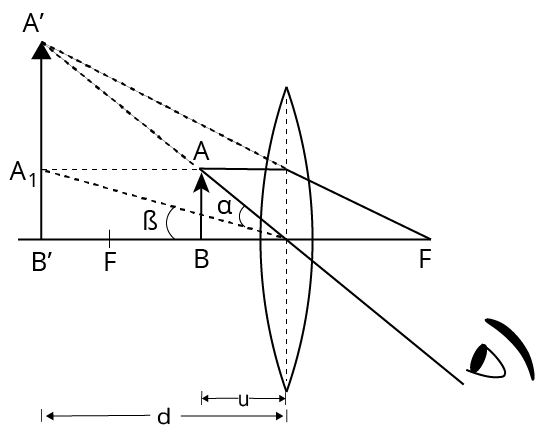
Simple Microscope
Magnification of Simple Microscope
When the final image is formed at a distance equal to or greater than the distinct vision distance,$M=1+\dfrac{D}{f}$
For relaxed eye, $M=\dfrac{D}{f}$ where, $D=$ least distance of distinct vision
Compound Microscope
It is made up of two coaxially arranged converging lenses. The one facing the object is known as the objective, while the one closest to the eye is known as the eye piece.
The objective's aperture and focal length are smaller than those of the eyepiece.
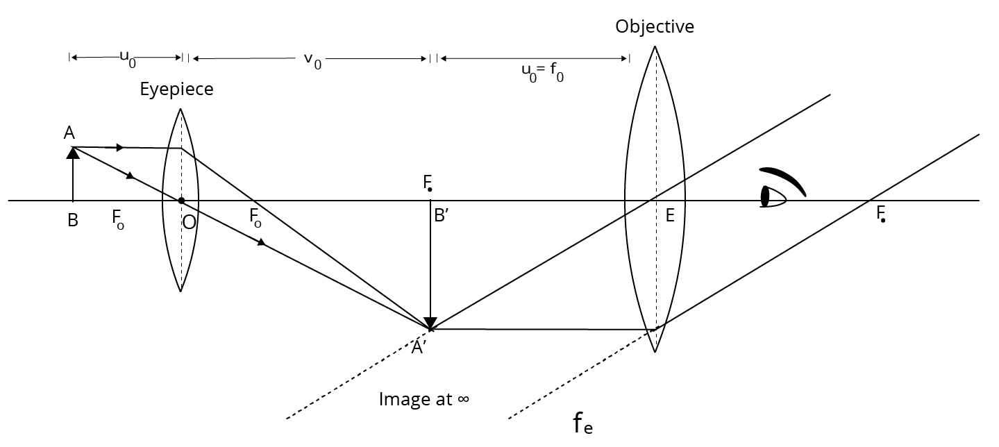
Compound Microscope
Magnification of Compound Microscope
When the final image is formed at the least distance of distinct vision, $m=-\dfrac{v_{0}}{u_{0}}\left(1+\dfrac{D}{f_{e}}\right)$
For the image formed at infinity, $u_{e}=f_{e}$and $m=-\dfrac{v_{0}}{u_{0}} \cdot \dfrac{D}{f_{e}}$
By making the focal length of the objective small, the magnifying power can be increased.
Telescope
A telescope is an optical instrument that increases the visual angle at the eye by forming an image of a distant object at the shortest distance of distinct vision, allowing the object to appear larger and more distinct.
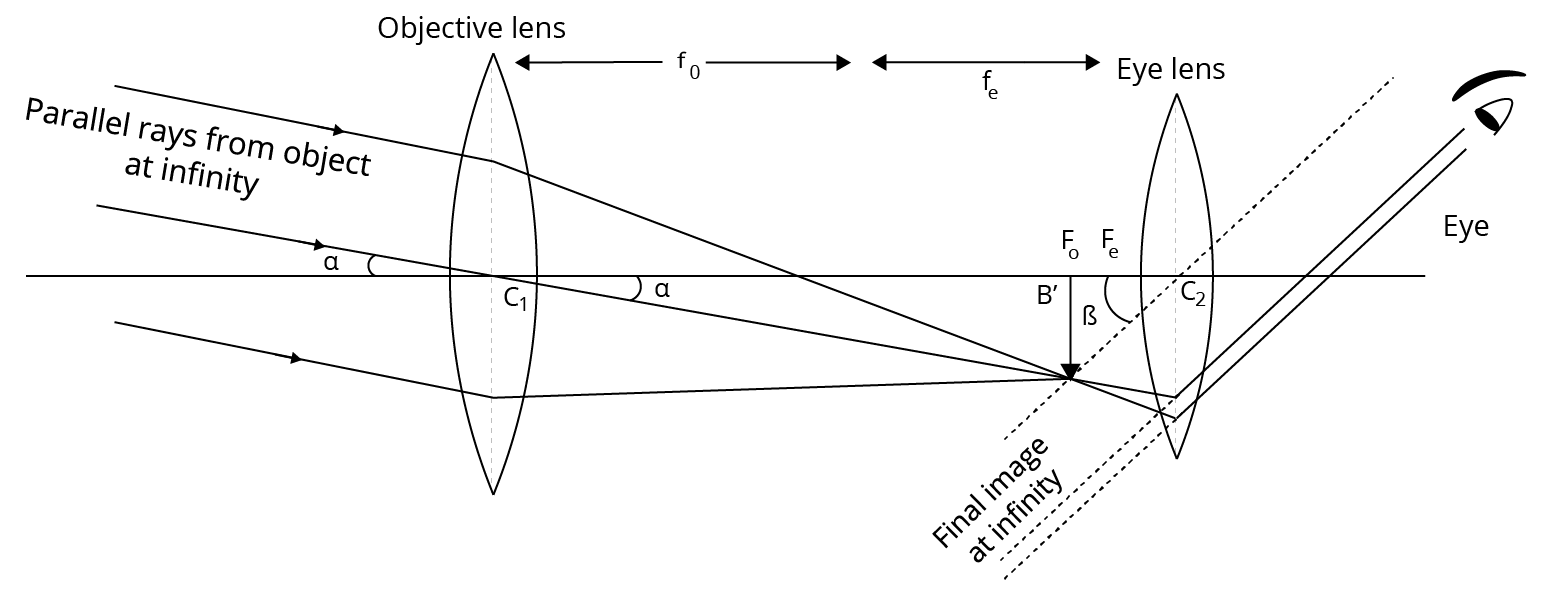
Astronomical Telescope
It is made up of two coaxially positioned converging lenses. The objective is the lens that faces the distant object and has a large aperture and focal length.
The other is known as the eyepiece because the eye is placed against it. The eyepiece tube slides inside the objective tube, allowing the distance between the objective and the eyepiece to be adjusted.
Magnification of Astronomical Telescope
For relaxed eye, $M_{\infty}=-\dfrac{f_{o}}{f_{e}}$ In this position, length of telescope, $L_{\infty}=f_{o}+f_{e}$
When final image is formed at least distance of distinct vision, $M_{D}=-\dfrac{f_{o}}{f_{e}}\left(1+\dfrac{f_{e}}{D}\right)$ Length of telescope, $L_{D}=f_{o}+f_{e}$ Here, $f_{o}=$ focal length of objective lens and $f_{e}=\text { focal length of eyepiece }$.
It is used to observe distinct images of celestial bodies such as stars, planets, and so on.
Two convex lenses with unequal focal lengths make up a refracting telescope.
Astronomical Telescope
Critical Angle:
The critical angle (C) is the angle of incidence in the denser medium for which the angle of refraction in the rarer medium is 90°.
$C = {\sin ^{ - 1}}\left( {\dfrac{1}{n}} \right)$
Lens’s Maker’s Formula:
$\dfrac{1}{f} = (n - 1)\left( {\dfrac{1}{{{R_1}}} - \dfrac{1}{{{R_2}}}} \right)$ , where n is the refractive index of the material of the lens with respect to the outer medium, R1 is the radius of curvature of the surface facing the object and R2 that of the other surface.
Prism Formula:
$n = \dfrac{{\sin \left( {\dfrac{{A + \delta }}{2}} \right)}}{{\sin \left( {\dfrac{A}{2}} \right)}}$, where $\delta $ is the minimum deviation and A is the angle of the prism.
Wave Optics:
Wave optics is based on the wave theory of light put forward by Huygen.
According to wave theory, light is a form of energy which travels through a medium in the form of transverse waves.
Light is a form of energy.
Light travels even in a vacuum. It does not require a material medium for its propagation.
Newton's Corpuscular Theory:
Light consists of extremely small, invisible elastic particles travelling in a vacuum with a speed of 3 × 10⁸ m/s.
The theory could explain reflection and refraction.
It could not explain interference, diffraction, polarisation, photoelectric effect and Compton effect. The theory failed as it could not explain why light travels faster in a rarer medium than in a denser medium.
Huygen's Wave Theory:
Light travels in a medium in the form of a wavefront where a wavefront is the locus of all the particles vibrating in the same phase.
When the source of light is a point source, the wavefront is spherical. Amplitude is inversely proportional to distance.
When the source of light is linear, the wavefront is cylindrical.
At a very large distance from the source (or an extended large source), a portion of spherical or cylindrical wavefront appears to the plane. In this case amplitude and intensity remains constant.
A wavefront travels parallel to itself and perpendicular to the rays.
Wavefront always travels in the forward direction of the medium.
In an anisotropic medium, a point source gives rise to an elliptic wavefront.
Huygen's wave theory could explain reflection, refraction, interference and diffraction of light.
It failed to explain polarisation of light. It assumed the light waves to be longitudinal and hence failed to explain polarisation. It also could not explain the backward propagation of light, photoelectric effect, Compton effect and Raman effect.
Maxwell's Electromagnetic Theory:
The electromagnetic waves are transverse waves which require no material medium for propagation. They can travel through vacuum.
Due to transverse nature, light waves undergo polarisation.
In these waves, the electric field vector and magnetic field vector vibrate in the same phase along mutually perpendicular directions.
The electric field vector and magnetic field vector are perpendicular to the direction of velocity of light.
It explained the phenomenon of reflection, refraction, interference, diffraction and polarisation.
It failed to explain the phenomenon of photoelectric effect, Compton effect and Raman effect.
Max Planck's Quantum Theory:
Light consists of packets of energy known as quanta or photons.
The photons are emitted discretely and not continuously.
The velocity of a photon is equal to that of light.
The rest mass of the photon = zero.
Photons are electrically neutral.
Quantum theory could explain the photoelectric effect, Compton effect and Raman effect.
Quantum theory failed to explain interference, diffraction and polarisation of light.
De-Broglie's Dual Theory:
Light behaves both as a corpuscle and also as waves.
The corpuscular and wave aspects are like the two faces of a coin which can never be separated. Light does not exhibit both the aspects simultaneously. In some phenomena it behaves like transverse waves (as in interference, diffraction and polarisation) and in other phenomena it behaves like particles (as in photoelectric effect, Compton effect and Raman effect). This dual theory explains all the phenomena and effects of light.
Huygen's Principle:
Every point on a given wavefront (called primary wave front) acts as a fresh source of new disturbance, called secondary wavelets.
The secondary wavelets travel in all directions with the speed of light in the medium.
A surface touching these secondary wavelets tangentially in the forward direction at any instant gives the new secondary wavefront at that instant.
Interference of Light
When two light waves of exactly equal frequency have a phase difference which is constant with respect to time travel in the same direction and overlap each other then the intensity is not uniform in space. The phenomenon of nonuniform distribution of energy in the medium due to superposition of two such light waves is called interference of light.
The interference pattern in which the position of maxima and minima of intensity of light remain fixed all along on the screen is called sustained or permanent interference pattern.
At the points where resultant intensity is maximum, interference is said to be constructive.
At the points where the resultant intensity is minimum, interference is said to be destructive.
The condition for constructive interference is that path difference between two waves should be zero or an integral multiple of full wavelength.
The condition for destructive interference is that path difference between two waves should be an odd integral multiple of half the wavelength.
Newton's rings are formed as a result of interference between the light waves reflected from the upper and a lower surface of the air film.
In the interference of the light waves, we obtain alternate bright and dark bands of light, called interference fringes.
Fringe width: The distance between the centres of two consecutive bright or dark fringes is called the fringe width.
The angular fringe width is given by θ = λ/d, where λ is the wavelength of light, d is the distance between two coherent sources.
Coherent Source:
Coherent sources are those which emit continuous light waves of same amplitude, same wavelength/frequency in the same phase or having a constant phase difference. Two independent sources can never be coherent. They are produced from a single source of light.
Thomas Young's Double Slit Experiment:
In this experiment, two points of the same wavefront are used as two coherent sources.
Interference fringes obtained in Young's experiment consist of alternate bright and dark bands.
All bright fringes have the same intensity and all dark fringes are perfectly dark.
Bright fringes are due to constructive interference. Dark fringes are due to destructive interference.
The central fringe is bright with monochromatic light. It is achromatic/white with white light.
For nth bright fringe, path difference = $\dfrac{{xd}}{D}$ = nλ.
For nth bright fringe, path difference = $\dfrac{{xd}}{D}$ = $\dfrac{{2n - 1}}{2}\lambda $.
Fringe width = $\dfrac{{\lambda D}}{d}$
n = order of fringe
x = distance of nth bright fringe from centre
d = distance between two coherent sources
D = distance between screen and slit/source
λ = wavelength of light
Diffraction of Light:
The act of bending light around corners such that it spreads out and illuminates regions, where a shadow is anticipated, is known as diffraction of light. Since both occur simultaneously, it is challenging to distinguish between diffraction and interference. The diffraction of light is what causes the silver lining we see in the sky. A silver lining appears in the sky when the sunlight penetrates or strikes the cloud.
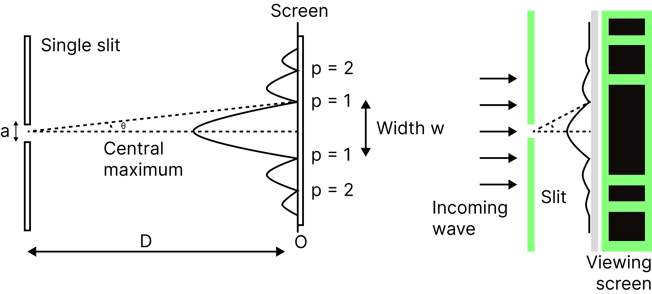
In Young's experiment, a single narrow slit in place of the double slit produced a broad pattern with a bright patch in the middle. Dark and bright sections alternate on either side of the centre. As one moves out from the centre, the intensity decreases. In this post, we go into great detail about the diffraction of light through a single slit.
Single Slit Diffraction
A bright and dark band appears on the screen when a monochromatic light beam strikes a single slit and is diffracted by the slit.
Maxima and minimum are other names for the bright pattern and the black band, respectively.
The intensity of light is at its highest point during maxima and its lowest point at minima.
Single Slit Diffraction
The width of the maxima is given by:
$a \sin \theta=n \lambda$
Where $\lambda$ is the wavelength of the light, $n$ is an integer value, a is slit width and $D$ is the distance of the screen from the slit.
Here if $\theta$ is very small (less than $\left.30^{\circ}\right) \sin \theta$ will be approximately equal to $\theta$.
Thus, for $m^{\text {th }}$ minima, the equation can be expressed as
$a \theta=m \lambda_m=\pm 1, \pm 2, \pm 3 \ldots$
$\text { I.e., } \theta=m \lambda / a, a \theta=m \lambda_m=\pm 1, \pm 2, \pm 3 \ldots$
The intensity of single-slit diffraction at some $m^{\text {th }}$ minima
Doppler's Effect in Light and Polarisation of Light:
The apparent shift in the frequency of the light that the observer perceives as a result of relative motion between the source of the light and the observer is known as the Doppler effect of light.
However, the equations for the Doppler shift for sound waves vary significantly depending on whether the source, the observer, or the air is moving.
Light doesn't need a medium to travel, and the observer and source relative speeds are the sole factors affecting the Doppler shift for light travelling in a vacuum.
The frequency that the observer receives will be lower than the frequency that the light source transmits as it moves away from the observer.
The visible light spectrum shifts towards the red end as a result. It's known as the redshift in astronomy.
The frequency perceived by the observer will be higher than the frequency broadcast by the source when the light source advances in that direction.
The visible light spectrum shifts in favour of the high-frequency region as a result. Scientists refer to it as the blue shift.
Polarisation of Light:
A characteristic of turning waves that demonstrates the geometrical blossoming of the oscillations is polarisation of light.
A turning wave oscillates at an angle of 90 degrees to the wave's velocity. The two waves of plane polarised light have the same mode of vibration for all waves.
Moving across space, electric and magnetic fields interact to form light. Light waves vibrate electrically and magnetically in opposition to one another. The magnetic and electric fields move perpendicular to one another in different directions. As a result, the direction of motion is perpendicular to both the plane occupied by the electric field and the plane of the magnetic field that is perpendicular to it.
These magnetic and electric vibrations can take place on various planes. Unpolarized light is a type of light wave that vibrates in more than one plane. The sun, a lamp, and a tube light are all examples of unpolarized light sources.
The propagation direction is constant, however, the planes on which the amplitude occurs are changing.
Polarised waves are another type of wave. Light waves that vibrate only in one plane are known as polarised waves. The waves that make up plane polarised light all have the same direction of vibration. Polarisation is the process through which non-polarized light is converted into polarised light.
Formula Chart:
1. Relation between focal length and radius of curvature of a mirror/lens, $\quad f=R$
2. Mirror formula: $\quad \dfrac{1}{\mathrm{f}}=\dfrac{1}{\mathrm{v}}+\dfrac{1}{\mathrm{u}}$
3. Magnification produced by a mirror:
$m=-\dfrac{v}{u}=-\dfrac{f}{u-f}$
4. Snell's law: $\quad \dfrac{\sin i}{\sin r}={ }^{1} n_{2}=\dfrac{n_{2}}{n_{1}}$
5. ${ }^{2}{ }_{1}=\dfrac{1}{1_{n 2}}$
6. $\mathrm{n}=\dfrac{\mathrm{c}}{\mathrm{v}}=\dfrac{\text { speed of light in vacuum }}{\text { speed of light in a medium }}=\dfrac{\lambda_{\text {air }}}{\lambda_{\text {medium }}}$
7. If object is in medium of refractive index $\mathrm{n}$, then $\mathrm{n}=\dfrac{\text { real depth }}{\text { apparent depth }}=\dfrac{t}{t_{a p p}}$
8. Apparent shift, $x=t-\dfrac{t}{n}=t\left(1-\dfrac{1}{n}\right)$
9. Critical angle for total internal reflection: $\quad \sin \mathrm{C}=\dfrac{1}{r^{n} \mathrm{~d}}=\dfrac{1}{n}$
10. Refraction at spherical (convex) surface: For object in rarer medium and real image in denser medium, the formula is $\dfrac{n_{2}}{v}-\dfrac{n_{1}}{u}=\dfrac{n_{2}-n_{1}}{R}$ where $n_{2} \& n_{1}$ are the refractive indices of denser and rarer media.
11. Lens formula:
$\dfrac{1}{\mathrm{f}}=\dfrac{1}{\mathrm{v}}-\dfrac{1}{\mathrm{u}}$
12. Linear magnification produced by a lens: $m=\dfrac{\mathrm{I}}{0}=\dfrac{\mathrm{v}}{\mathrm{u}}$
13. Lens maker's formula : $\dfrac{1}{\mathrm{f}}=\dfrac{1}{\mathrm{v}}-\dfrac{1}{\mathrm{u}}=\left({ }^{a} n_{\mathrm{g}}-1\right)\left[\dfrac{1}{\mathrm{R}_{1}}-\dfrac{1}{\mathrm{R}_{2}}\right]=(\mathrm{n}-1)\left[\dfrac{1}{\mathrm{R}_{1}}-\dfrac{1}{\mathrm{R}_{2}}\right]$
14. Power of a lens: $P=\dfrac{1}{f}$ diopter
( $f$ is in metre)
15. Lenses in contact: $\dfrac{1}{\mathrm{f}}=\dfrac{1}{\mathrm{f}_{1}}+\dfrac{1}{\mathrm{f}_{2}} \quad$ or $\quad \mathrm{P}=\mathrm{P}_{1}+\mathrm{P}_{2}$
Example 1: A glass tumbler having an inner depth of $17.5 \mathrm{~cm}$ is kept on a table. A student starts pouring water $(\mu=4 / 3)$ into it while looking at the surface of water from the above. When he feels that the tumbler is half filled, he stops pouring water. Up to what height, the tumbler is actually filled?
(A) $11.7 \mathrm{~cm}$
(B) $10 \mathrm{~cm}$
(C) $7.5 \mathrm{~cm}$
(D) $8.75 \mathrm{~cm}$
Answer: B
Explanation:
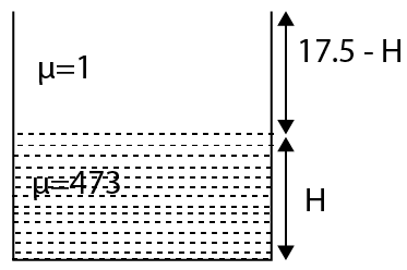
Glass Tumbler
Consider the actual height of the tumbler be $\mathrm{H}$.
The refractive index of the water, $\mu=4 / 3$
The refractive index of the air, $\mu=1$
As we know that,
$\mu_{\text {water }}=\dfrac{H_{\text {real }}}{H_{\text {apparent }}} \Rightarrow \dfrac{4}{3}=\dfrac{H}{H_{\text {apparent }}} $
$\Rightarrow H_{\text {apparent }}=\dfrac{3 H}{4}$
Height of air observed by observer $=17.5-\mathrm{H}$
According to the question, both heights observed by observers are the same.
$\dfrac{3 H}{4}=17.5-\mathrm{H}$
$\Rightarrow \mathrm{H}=10 \mathrm{~cm}$
Hence, the correct answer is option B.
Example 2: Two plane mirrors $\mathrm{M}_{1}$ and $\mathrm{M}_{2}$ are at right angles to each other shown. A point source 'P' is placed at 'a' and '2a' meters away from $\mathrm{M}_{1}$ and $\mathrm{M}_{2}$ respectively. The shortest distance between the images thus formed is : (Take $\sqrt{5}=2.3)$
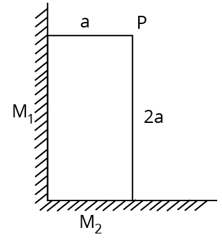
Two Plane Mirror
(A) $3 a$
(B )$4.6 a$
(C) $2.3 a$
(D) $2 \sqrt{10} a$
Answer: B
Explanation:
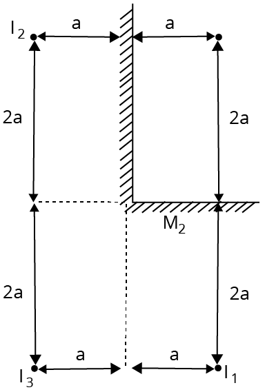
Plane Mirror Construction
Shortest distance is $2 \mathrm{a}$ between $\mathrm{I}_{1} \& \mathrm{I}_{3}$
But answer given is for $\mathrm{I}_{1} \& \mathrm{I}_{2}$
$=\sqrt{(4 a)^{2}+(2 a)^{2}} $
$=a \sqrt{20} $
$=4.47 \mathrm{a}$
Hence, the correct answer is option B.
Importance of Class 12 Physics Chapter Optics
You have studied light rays, their reflection, refraction, and the formulae related to all these scientific principles. In this chapter on optics, you will be introduced to the advanced concepts along with what you have studied in the previous classes.
The fundamental concepts of ray optics and the mechanism of optical instruments will be taught in this chapter. Students will be introduced to the advanced concepts related to rectilinear propagation of light, the reflection of light on a plane and curved surfaces, refraction of light in transparent mediums, and linear magnification of images.
They will also study lenses and how different types of lenses are used in the optical instruments used these days. The scientific terms related to the lenses and spherical mirrors will also be explained with proper terminologies to represent them. The formulae used to determine the value of these terms will also be explained.
This chapter is very important for the preparation for the JEE Advanced exam. Conceptual questions from this chapter appear in the exam. Preparing this chapter will help you understand the basic and advanced principles of optics and score good marks in the competitive exams.
Benefits of Vedantu’s Optics Revision Notes for JEE Advanced
Optics notes are compiled by the experts of Vedantu to offer a simpler version of the crucial principles of this chapter. You will learn these scientific principles faster using these revision notes and keep yourself ahead of your class.
These Optics revision notes for JEE Advanced can be used for revising this chapter faster. The concise presentation of all the sections of this chapter will help you reduce your revision time. In fact, you can also recall the concepts, formulae, and derivations you have studied in this chapter by following the organised presentation of the notes.
Use these notes at your convenience and make your study sessions much better. You can download and refer to these notes at your convenience. Simplify your knowledge development process and quickly find out the answers to the questions coming in the competitive exams.
Follow the sample questions in these notes to evaluate your preparation level. Find out where you need to concentrate more and fortify your conceptual foundation for this chapter.
JEE Advanced Optics Notes PDF Download
Get the free PDF version of these notes and complete your study material for optics. These notes are compiled to offer a better platform for understanding, studying, revising, and recalling the fundamental concepts of optics for the JEE Advanced exam. Follow how the experts have simply explained these concepts and escalate your answering skills to score more in the exam.
Conclusion
The JEE Advanced Optics Notes offer a structured approach to mastering ray and wave optics, covering key topics like reflection, refraction, lenses, mirrors, and diffraction. With well-organised formulas, solved examples, and clear explanations, these notes simplify complex concepts and enhance problem-solving skills. Download the JEE Advanced Optics Notes PDF to revise efficiently, strengthen concepts, and boost confidence for the exam. Prepare smarter with Vedantu’s expert-curated study material and achieve your dream score!
Important Related Links for JEE Main and JEE Advanced

FAQs on JEE Advanced Optics Notes 2026
1. What is a lens?
A lens is an optical instrument made of glass or any transparent material used to divert light rays.
2. What is a spherical mirror?
A spherical mirror is a section of a sphere that has a reflecting surface inside or outside the curvature.
3. What is a focus in a lens?
A focus is a point on the principal axis of a lens where incident parallel rays meet.
4. What happens to the light rays emerging from the focal point?
Light rays emerging from the focus will become parallel to each other after refraction in a lens.
5. Where can I find the JEE Advanced Optics Notes PDF Download for free?
You can download the JEE Advanced Optics Notes PDF for free from Vedantu. These expert-curated notes cover key concepts, formulas, and problem-solving techniques to help you ace the exam.
6. How can JEE Advanced Physics Optics Notes help in exam preparation?
The JEE Advanced Physics Optics Notes provide a clear understanding of topics like reflection, refraction, mirrors, and lenses. These notes include important formulas, shortcut tricks, and solved examples, making it easier to grasp complex concepts and score well in the exam.
7. What topics are covered in JEE Advanced Optics Notes?
The JEE Advanced Optics Notes include:
Reflection and refraction of light
Laws of reflection and refraction
Mirrors and lenses
Image formation and focal length
Total internal reflection
Wave optics, interference, and diffraction
Optical instruments like microscopes and telescopes
8. Are the JEE Advanced Optics Notes available in PDF format?
Yes, the JEE Advanced Optics Notes PDF Download is available for free on Vedantu. The PDF format allows you to access the notes anytime and revise important concepts on the go.
9. What is the difference between real and virtual images?
Real Image: Formed when light rays meet, can be projected on a screen and is always inverted.
Virtual Image: Formed when light rays appear to meet, cannot be projected and is always upright.
Example:
Real image → Formed by concave mirrors at certain positions.
Virtual image → Formed by plane and convex mirrors.
10. What is wave optics and how is it different from ray optics?
Ray optics (Geometrical Optics): Deals with the straight-line propagation of light (reflection, refraction, and mirror/lens formulas).
Wave optics (Physical Optics): Explains interference, diffraction, and polarisation, treating light as a wave.
11. What are the key applications of optics in daily life?
Optics plays a crucial role in:
Eyeglasses & contact lenses (vision correction)
Cameras & telescopes (image formation)
Microscopes (magnification of small objects)
Laser technology (medical and industrial applications)
Optical fibres (telecommunication and internet)
12. Are Optics questions difficult in JEE Advanced?
Optics in JEE Advanced is moderate to difficult. The Ray Optics section is generally formula-based, while Wave Optics requires conceptual understanding. Many questions involve total internal reflection, lenses, and interference patterns.
13. What is the weightage of Optics in JEE Advanced?
Optics carries 12-15% weightage in the JEE Advanced Physics paper. Topics like reflection, refraction, wave optics, and optical instruments are commonly tested.