


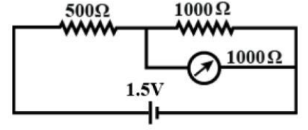
The resistance 500$\Omega $ and 1000$\Omega$ are connected in series with a battery of 1.5 volts. The voltage across the 1000 ohm resistance is measured by a voltmeter having a resistance of 1000 $\Omega $. The reading in the voltmeter would be:
A) 1.5 volt
B) 1.0 volt
C) 0.75 volt
D) 0.5 volt
Answer
233.1k+ views
Hint: A voltmeter is an instrument used for measuring potential difference or voltage levels between any two points in a circuit when connected in parallel to the portion of the circuit for which the voltage is to be measured. Voltmeters can be used for measuring voltage drop. Voltage is always measured across or in parallel to the circuits.
Complete step by step solution:
Let I be the total current flowing in the circuit which subsequently gets divided into I’ flows through both the resistance of 1000 ohm and the voltmeter, as shown in the following figure.
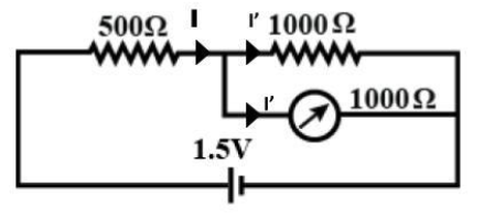
As the voltmeter and the resistance of 1000 ohm are in parallel and both of them have a resistance of equal magnitude, so the current will be equally distributed among them. Hence, we can say that,
$I' = \dfrac{I}{2}$ …………… (1)
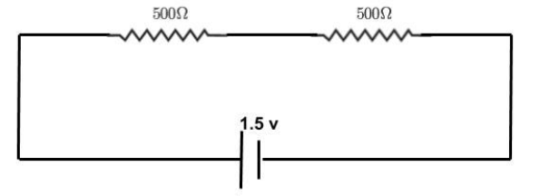
As there are two resistances in parallel each of which has a magnitude of 1000 ohms hence the equivalent resistance is given by,
${R_{eq}} = \dfrac{{1000 \times 1000}}{{1000 + 1000}}$
${R_{eq}} = 500\Omega $
The equivalent circuit is shown in the following circuit diagram.
The total current (I) flowing through the circuit is given by,
$I = \dfrac{V}{R}$
$ \Rightarrow I = \dfrac{{1.5}}{{500 + 500}}$
$ \Rightarrow I = 1.5 \times {10^{ - 3}}A$
Now from equation (1) current I’ is given by,
$I' = \dfrac{{1.5 \times {{10}^{ - 3}}}}{2}$
$ \Rightarrow I' = 0.75 \times {10^{ - 3}}A$
We know that the voltmeter reading (VR) can be obtained by multiplying the current flowing through it and its own resistance. Mathematically it is given by,
${V_R} = I' \times 1000\Omega $
$\therefore {V_R} = 0.75V$
Since the reading on the voltmeter is found to be 0.75 volts hence we can say that option C is the current answer.
Note: We have already discussed the voltmeter in the above section. A voltmeter is an important measuring device in electrical measurements but there is another important device known as ammeter which needs to be mentioned here. An ammeter is a device which measures the current flowing in a circuit. An ammeter is connected in parallel to the part of the circuit whose current is to be measured.
Complete step by step solution:
Let I be the total current flowing in the circuit which subsequently gets divided into I’ flows through both the resistance of 1000 ohm and the voltmeter, as shown in the following figure.
As the voltmeter and the resistance of 1000 ohm are in parallel and both of them have a resistance of equal magnitude, so the current will be equally distributed among them. Hence, we can say that,
$I' = \dfrac{I}{2}$ …………… (1)
As there are two resistances in parallel each of which has a magnitude of 1000 ohms hence the equivalent resistance is given by,
${R_{eq}} = \dfrac{{1000 \times 1000}}{{1000 + 1000}}$
${R_{eq}} = 500\Omega $
The equivalent circuit is shown in the following circuit diagram.
The total current (I) flowing through the circuit is given by,
$I = \dfrac{V}{R}$
$ \Rightarrow I = \dfrac{{1.5}}{{500 + 500}}$
$ \Rightarrow I = 1.5 \times {10^{ - 3}}A$
Now from equation (1) current I’ is given by,
$I' = \dfrac{{1.5 \times {{10}^{ - 3}}}}{2}$
$ \Rightarrow I' = 0.75 \times {10^{ - 3}}A$
We know that the voltmeter reading (VR) can be obtained by multiplying the current flowing through it and its own resistance. Mathematically it is given by,
${V_R} = I' \times 1000\Omega $
$\therefore {V_R} = 0.75V$
Since the reading on the voltmeter is found to be 0.75 volts hence we can say that option C is the current answer.
Note: We have already discussed the voltmeter in the above section. A voltmeter is an important measuring device in electrical measurements but there is another important device known as ammeter which needs to be mentioned here. An ammeter is a device which measures the current flowing in a circuit. An ammeter is connected in parallel to the part of the circuit whose current is to be measured.
Recently Updated Pages
JEE Main 2026 Session 2 Registration Open, Exam Dates, Syllabus & Eligibility
JEE Main 2023 April 6 Shift 1 Question Paper with Answer Key
JEE Main 2023 April 6 Shift 2 Question Paper with Answer Key
JEE Main 2023 (January 31 Evening Shift) Question Paper with Solutions [PDF]
JEE Main 2023 January 30 Shift 2 Question Paper with Answer Key
JEE Main 2023 January 25 Shift 1 Question Paper with Answer Key
Trending doubts
Why does capacitor block DC and allow AC class 12 physics JEE_Main
Understanding Average and RMS Value in Electrical Circuits
Ideal and Non-Ideal Solutions Explained for Class 12 Chemistry
Understanding Atomic Structure for Beginners
Understanding Elastic Collisions in Two Dimensions
JEE Main Syllabus 2026: Download Detailed Subject-wise PDF
Other Pages
MOSFET: Definition, Working Principle, Types & Applications
Understanding Collisions: Types and Examples for Students
Happy New Year Wishes 2026 – 100+ Messages, Quotes, Shayari, Images & Status in All Languages
Valentine Week 2026 List | Valentine Week Days, Dates & Meaning
One Day International Cricket- India Vs New Zealand Records and Score
Highest T20 Scores in Cricket: Top Records & Stats 2025