


Revision Notes on Communication Systems for NEET 2026 - Free PDF Download
Communication
The act of transmitting information is referred to as communication. Every living thing on the planet constantly urges to share or receive information with others in its environment.
A shared language between the sender and the receiver is necessary for effective communication. Man has consistently worked to enhance the effectiveness of human communication.
Elements of a Communication System
All living things communicate at all phases of their lives. Regardless of the type, every communication system needs three components: the transmitter, the medium or channel, and the receiver.
There are Two Basic Modes of Communication: Point-to-point and Broadcast.
In point-to-point communication mode, just one transmitter and one receiver are involved in the communication over the link. One such method of communication is telephony. In contrast, there are much more receivers than transmitters when using the broadcast mode. As examples of broadcast media, consider radio and television.
Digital and analogue signals cannot be transferred as such since they are often low-frequency transmissions.
Some carriers must be used to transport these signals. These carriers are also referred to as high-frequency signals or carrier waves.
Modulation is the process of overlaying a high frequency (HF) signal with a low frequency (LF) signal.
Basic Terminology Used in Electronic Communication Systems
Transducer: A transducer is any device that changes one type of energy into another. We frequently encounter gadgets in electronic communication systems that have electrical inputs or outputs.
Signal: A signal is a piece of information that has been electrically transformed into a form that can be transmitted. Analog or digital signals are both acceptable. A continuous voltage or current variations are analogue signals. They are essentially time functions with a single value.
An essential analogue signal is the sine wave. The sine wave components of all other analogue signals allow for a complete understanding of those signals. Analog transmissions are used in TV for both sound and picture.
Signals classified as digital can only have discrete, sequential values. The binary system, which is widely used in digital electronics, uses merely two levels of a signal: "0" stands for a low level of voltage or current, while "1" stands for a high level.
Noise: Unwanted signals that tend to interfere with the transmission and processing of message signals in a communication system are referred to as noise. The noise's source could be either inside the system or outside.
Transmitter: In order to prepare the incoming message signal for broadcast across a channel and subsequent receipt, a transmitter processes it.
Receiver: At the channel output, a receiver separates the required message signals from the received signals.
Attenuation: Attenuation is the signal power reduction as it travels across a medium.
Amplification: It involves utilising an electronic circuit called an amplifier to increase a signal's amplitude (and therefore its power). In communication systems, amplification is required to make up for signal attenuation. The energy required for increased signal strength is obtained from a DC power supply. Anywhere the signal intensity drops below the necessary level between the source and the destination, amplification is performed.
Range: It is the greatest separation between a source and a destination at which the signal can be reliably received.
Bandwidth: The frequency range that a piece of equipment may work over or the area of the spectrum that the signal occupies are both referred to as bandwidth.
Modulation: To prevent the initial low-frequency message/information signal from being transmitted over great distances. As a result, at the transmitter, data from the low-frequency message signal is overlaid on a high-frequency wave that serves as the data's carrier. Modulation is the term for this action. AM, FM, and PM are three different types of modulation, which will be further discussed.
Demodulation: Demodulation refers to the procedure at the receiver when information is retrieved from the carrier wave.
Repeater: A repeater combines a transmitter and a receiver. The signal from the transmitter is picked up by a repeater, which amplifies it and then retransmits it to the receiver—sometimes with a different carrier frequency. Repeaters are utilised to increase a communication system's range. A communication satellite functions as an orbiting repeater station.
Bandwidth of Signals
The message signal in a communication system may take the form of voice, music, a picture, or computer data. These signals each have a different frequency range. Depending on the band of frequencies thought to be crucial for transmission, a specific signal will require a specific type of communication system.
Bandwidth Of Transmission Medium
Different types of transmission media offer a range of bandwidths, much like message signals. Wire, open space and fibre optic cable are the three most often utilised transmission media. The bandwidth of coaxial cable, a commonly utilised wire media, is about $750 \mathrm{MHz}$. These cables are often operated at frequencies lower than $18 \mathrm{GHz}$. Radio waves are used for communication over free space at a very wide range of frequencies, from a few hundreds of kHz to a few GHz.
Propagation of Electromagnetic Waves In Atmosphere:
When emitted from a transmitting antenna, radio waves, also known as electromagnetic waves, travel across space to distant locations where they are picked up by the receiving antenna.
The pressure of the atmosphere, rain, snow, etc., do not affect these waves.
They can pass through non-metallic things, but metals greatly attenuate them.
They can spread without the aid of any material medium.
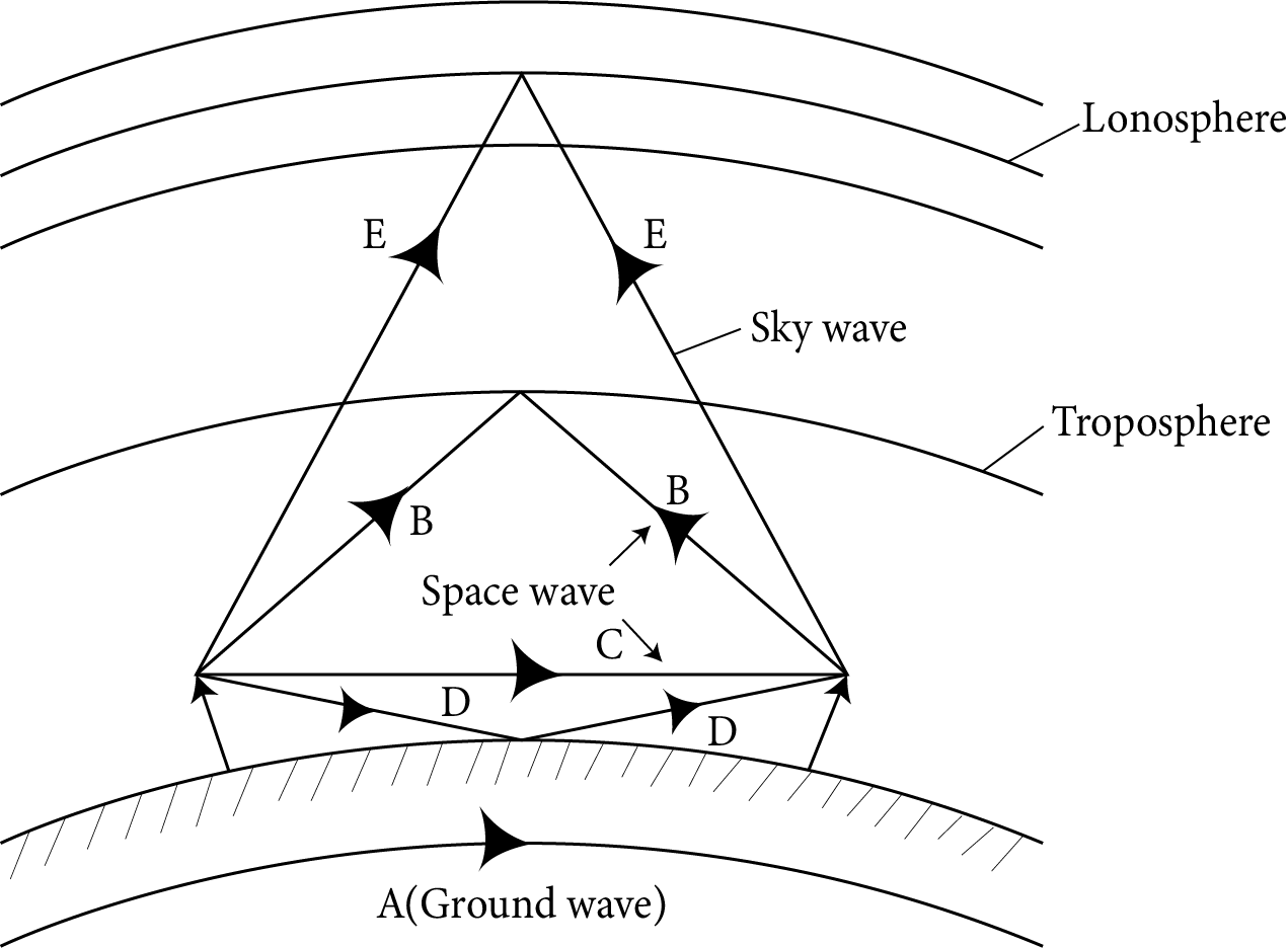
The following three radio wave propagation modes are based on the distinct ways radio waves of various wavelengths interact with the atmosphere.
Ground or surface wave propagation.
Space or tropospheric wave propagation.
Sky or ionospheric wave propagation.
Surface Wave Propagation:
In this mode, the earth directs the radio waves, which move from the transmitter to the receiver along the earth's curving surface.
There are two types of surface wave propagations.
Propagation of surface waves across short distances
Propagation of surface waves across great distances.
Surface field strength increases when the separation between the transmitting and receiving antennas is small.
Surface wave propagation for a flat surface is $E_{S}=\frac{E_{O}}{d} A$
The above equation (1) is applicable for distance upto $100 \sqrt[3]{\mathrm{f}} \mathrm{km}$ ( $\mathrm{f}=$ frequency in $\mathrm{MHz}$ ).
Distance $>100 \sqrt[3]{f k m}$ equation (1) has to be modified to take into account the curvature of earth.
For long-distance propagation, the reduction in field strength is due to the curvature of the earth.
Space Wave Propagation:
The definition of space wave propagation applies to radio waves that travel within 20 km of the troposphere and are made up of both direct and reflected waves. As they can go directly from the surface of the earth to the troposphere, these waves are also referred to as tropospheric propagation. Since the signals are sent in a straight line from the transmitter to the receiver, it is sometimes referred to as line of sight propagation.
Space Wave Propagation
The antennas' heights and separations can be specified as follows to avoid attenuation and signal strength loss:
$D_{m}=\left(2 \mathrm{RH}_{t}\right)^{-1 / 2}+\left(2 \mathrm{RH}_{\mathrm{r}}\right)^{-1 / 2}$
Where,
$\mathrm{D}_{\mathrm{m}}$ : distance between the two antennas
R: radius of the earth
$\mathrm{H}_{\mathrm{t}}$ : height of transmission antenna
$\mathrm{H}_{\mathrm{r}}$ : height of receiver antenna
Sky-Wave Propagation:
Radio communications over great distances require a technique called ionospheric propagation. Due to route bending brought on by ionisation in the higher air layer, the energy content of the wave in this form of propagation reaches the receiving antenna (ionosphere). The ionisation in the ionosphere is not uniform but it is stratified, i.e. in the form of layers. The layers are designed as $\mathrm{D}, \mathrm{E}, \mathrm{F}$ and $\mathrm{F}_{2}$ layers.
Modulation and its necessity
A communication system's main objective is to send information or message signals, as was already established. Baseband signals, which effectively refer to the band of frequencies that represents the initial signal as transmitted by the information source, are another name for message signals. The signal bandwidth is the range of frequencies that the signal spans because, in general, no signal has a single frequency sinusoid. Let's say we want to send an electronic signal straight over a long distance in the audio frequency (AF) range $(20 \mathrm{kHz}$ or less for baseband signals).
Size of the antenna or aerial
An antenna or aerial is required for signal transmission. In order for the antenna to accurately perceive the time variation of the signal, it must be at least $\lambda / 4$ in diameter and have a size comparable to the wavelength of the signal. The wavelength $\lambda$ of an electromagnetic wave with a frequency of $20 \mathrm{kHz}$ is $15 \mathrm{~km}$. It should go without saying that such a long antenna is impossible to build and maintain.
Effective power radiated by an antenna
According to a theoretical analysis of radiation from a linear antenna, the power emitted is proportional to $(\ell / \lambda)^{2}$. This suggests that the power emitted increases with decreasing $\lambda$, or rising frequency, for a given antenna length. Therefore, a long-wavelength baseband signal would have little effective power. High powers are required for effective transmission, which highlights the necessity of adopting high-frequency transmission.
Mixing up of signals from different transmitters
Another compelling defence against the direct transmission of baseband signals is more pragmatic in character. Let's say a lot of individuals are chatting at once or a lot of transmitters are sending baseband information signals at once. Because it will be difficult to tell one signal from another when they are mixed up,
This suggests a potential solution, which involves leveraging high-frequency communication and allocating a band of frequencies for the delivery of each message signal.
According to the aforementioned considerations, it is necessary to convert the original low-frequency baseband message or information signal into a high-frequency wave before transmission so that the translated signal retains the original signal's information.
Different types of pulse modulation are:
pulse amplitude modulation (PAM),
pulse duration modulation (PDM) or pulse width modulation (PWM), and
pulse position modulation (PPM).
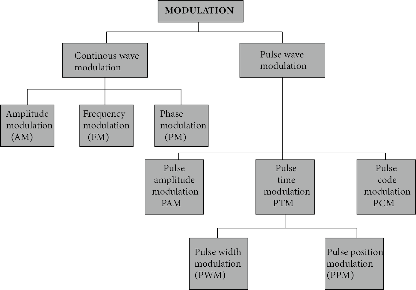
Modulation
Amplitude Modulation
In amplitude modulation, the carrier's amplitude changes in response to the information stream. Here, a sinusoidal signal is used as the modulating signal to explain the amplitude modulation process.
If $\mathrm{c}(\mathrm{t})=\mathrm{A}_{c} \sin \omega_{c} \mathrm{t}$ represent carrier wave and $\mathrm{m}(\mathrm{t})=\mathrm{A}_{\mathrm{m}} \sin \omega_{\mathrm{m}} \mathrm{represent}$ the message or the modulating signal where $\omega \mathrm{m}=2 \pi f_{\mathrm{m}}$ is the angular frequency of the message signal. The modulated signal $\mathrm{C}_{m} (t)$ can be written as
$C_{m}(t)=\left(A_{c}+A_{m} \sin \omega_{m t} t\right) \sin \omega_{c} t$
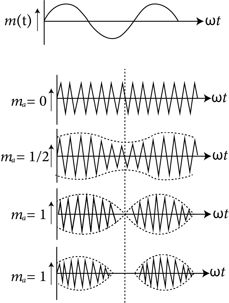
Modulation index:The modulation factor, degree of modulation, or modulation index is the ratio of the carrier wave's change amplitude to its initial amplitude.
$\left(\mathrm{m}_{\mathrm{a}}\right)$.
Here k=A factor which determines the maximum change in the amplitude for a given amplitude $E_{m}$ of the modulating. If k=1 then $m_{a}=\dfrac{A_{m}}{A_{a}}=\dfrac{A_{\max }-A_{\min }}{A_{\max }-A_{\min }}$
Angular Modulation
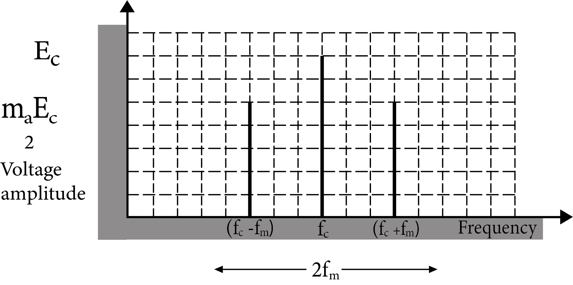
Side band frequencies and bandwidth in AM wave
Side band frequencies: The AM wave contains three frequency $f_{c},\left(f_{c}+f_{m}\right) and \left(f_{c}-f_{m}\right), f_{c}$ is called carrier frequency,
$\left(f_{c}+f_{m}\right)$ : Upper side band (USB) frequency
$\left(f_{c}-f_{m}\right)$ : Lower side band (LBS) frequency
Side band frequencies are generally close to the carrier frequency.
Band width : The two sidebands lie on either side of the carrier frequency at equal frequency intervals $\mathrm{fm}_{\mathrm{m}}$.
So, band width $=\left(f_{c}+f_{m}\right)-\left(f_{c}-f_{m}\right)=2 f_{m}$
Band width
Power in AM waves: Power dissipated in any circuit $P=\dfrac{V_{\mathrm{rms}}^{2}}{R}$.
Hence (i) carrier power $P_{c}=\dfrac{\left(\dfrac{A_{c}}{\sqrt{2}}\right)^{2}}{R}=\dfrac{A_{c}^{2}}{2 R}$
(ii) Total power of sidebands $P_{s b}=\dfrac{\left(\dfrac{m_{a} A_{c}}{2 \sqrt{2}}\right)^{2}}{R}=\dfrac{\left(\dfrac{m_{a} A_{c}}{2 \sqrt{2}}\right)}{2 R}=\dfrac{m_{a}^{2} A_{c}^{2}}{4 R}$
(iii) Total power of $\mathrm{AM} wave \mathrm{P}_{\text {Total }}=\mathrm{P}_{\mathrm{c}}+\mathrm{P}_{\mathrm{ab}}=\dfrac{\mathrm{A}_{\mathrm{c}}^{2}}{2 \mathrm{R}}\left(1+\dfrac{\mathrm{m}_{\mathrm{a}}^{2}}{2}\right)$
(iv) $\dfrac{P_{t}}{P_{c}}=\left(1+\dfrac{m_{a}^{2}}{2}\right)$
and $\dfrac{P_{\mathrm{sb}}}{P_{t}}=\dfrac{m_{a}^{2} / 2}{\left(1+\dfrac{m_{a}^{2}}{2}\right)}$
Limitation of amplitude modulation
Noisy reception
Low efficiency
Small operating range
Poor audio quality
Production of Amplitude Modulated Wave:
There are numerous ways to achieve amplitude modulation. The block diagram in figure illustrates a conceptually straightforward method.
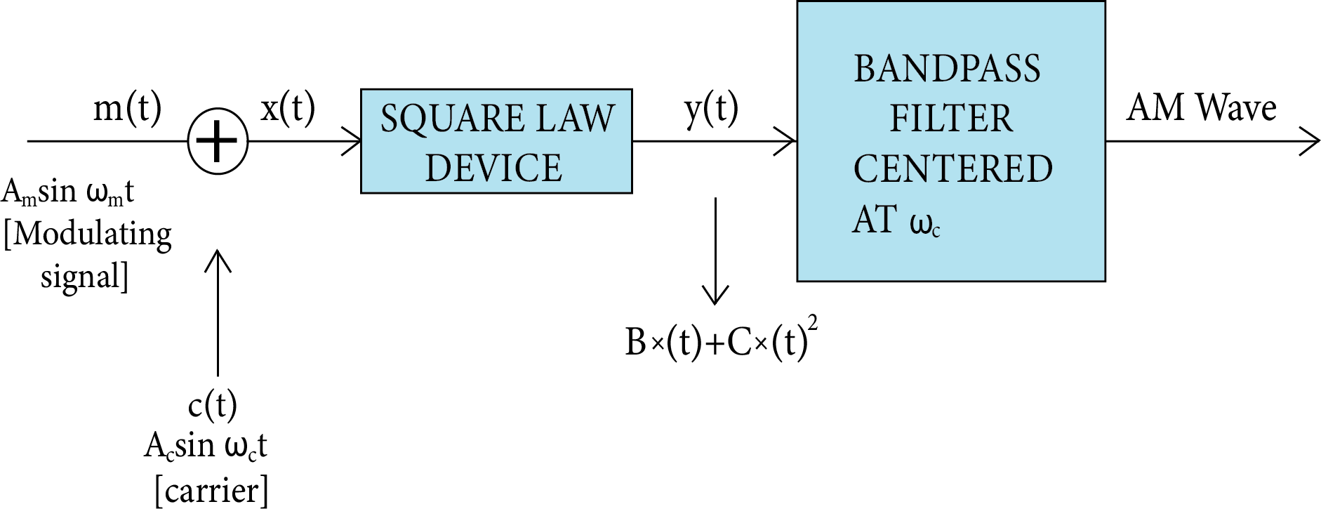
Production of Amplitude Modulated Wave
Detection of Amplitude Modulated Wave
When a message is transmitted, it weakens as it travels across the channel. An amplifier and a detector should consequently come after the receiving antenna. Additionally, the carrier frequency is typically shifted to a lower frequency by what is known as an intermediate frequency (IF) step prior to the detection to aid in further processing. It may be necessary to amp up the detected signal because it might not be powerful enough to be useful. Figure displays a block diagram of a typical receiver.
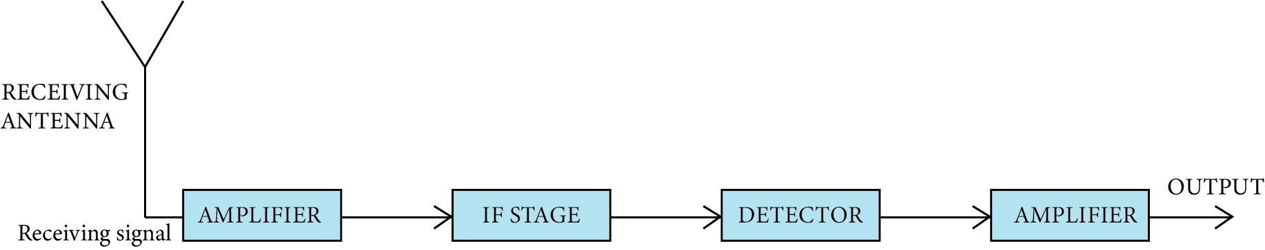
Typical Receiver
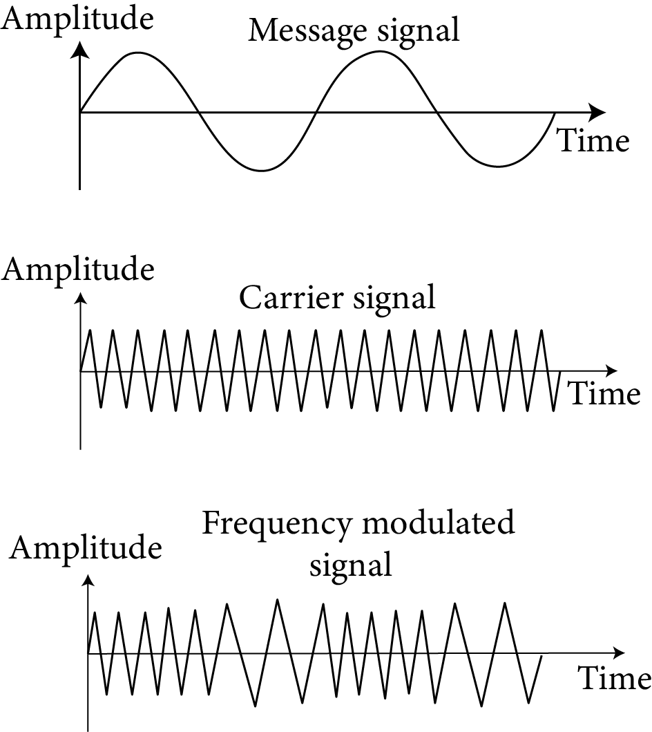
Frequency Modulation
It is the second variety of sinusoidal or continuous wave modulation.
The frequency of the carrier signal fluctuates in this kind of modulation in response to the modulating signal. While the carrier wave's frequency changes, its amplitude remains constant.
In frequency modulation, the amplitude of the modulating wave causes a change in the carrier wave's frequency.
At all times, the carrier's amplitude is constant. In other words, both the carrier wave's amplitude and the modulated wave's amplitude are maintained. The carrier's frequency is made to oscillate symmetrically above and below its unmodulated frequency. As an example, a carrier frequency, of $1000 \mathrm{kHz}$ may be caused to swing between $925 \mathrm{kHz}$ and $1075 \mathrm{kHz}$
Frequency modulation equations mainly consist of a sinusoidal expression with the integral of the baseband signal that can be either a sine or cosine function.
It can be represented mathematically as;
$m(t)=A_{m} \cos \left(\omega_{m} t+\theta\right)$
$\mathrm{m}(\mathrm{t}) \rightarrow$ modulating signal
Where,
$A_{m} \rightarrow$ Amplitude of the modulating signal.
$\omega_{m} \rightarrow$ Angular frequency of the modulating signal.
$\theta \rightarrow$ is the phase of the modulating signal.
Such as amplitude modulation, when we try to modulate an input signal (information), we need a carrier wave,
we will experience
$C(t)=A_{c} \cos \left(\omega_{c} t+\theta\right) \ldots \ldots \ldots . .2$
Angular modulation, which means $\omega_{c}$ (or) $\theta$ of the carrier wave, starts varying linearly with respect to the modulating signal like amplitude modulation.
Side Band Frequency
If we look at the graph, we can see that as the input signal's amplitude grows, a carrier's frequency rises. When the input signal is strongest in this case, the carrier frequency is at its highest. In the meantime, if the modulating signal's amplitude falls, the frequency of a carrier also does. In other words, when the input signal is at its weakest, the carrier frequency is at its lowest.
Periodic Modulation (FM)
Frequency modulation is the process of altering a carrier wave's frequency to match an audio frequency signal.
The AM transmission's audio quality is subpar. It is necessary to get rid of amplitude-sensitive noise. If we take away the amplitude variation, this is feasible (i.e., a need to keep the amplitude of the carrier constant). In FM, this is exactly what we do.
The overall amplitude of the FM wave is always constant.
The overall transmitted power in FM does not change.
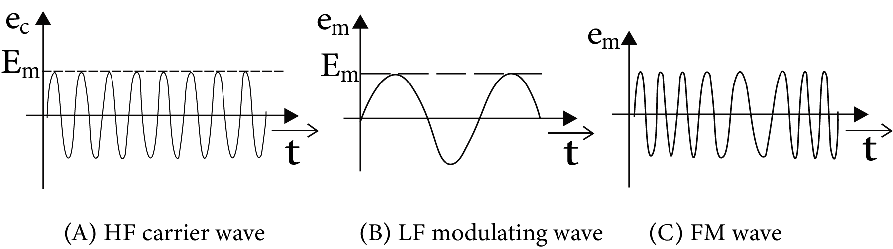
Different Types of Wave
Communication Modulated By Frequency (Height of Transmitting Antenna)
There is frequency modulation in TV transmissions. Ground wave propagation cannot be used to gain their transmission. This occurs as a result of the signals' high frequency being absorbed by the ground.
Additionally undesirable is communication via sky wave propagation. This is because the ionosphere can't reflect radio waves with frequencies higher than 40 MHz.
The receiving antenna must directly capture the signal from the sending antenna for TV broadcasts to be transmitted.
The waves that are being sent, moving directly in a straight path.
Simple Demodulator Circuit
Amplitude modulated (AM) waves can be detected or demodulated using a diode. A diode essentially performs the function of a rectifier by reducing the modulated carrier wave to just the positive envelope.
The figure depicts the AM wave input. It appears as a rectified wave at the diode's output across PQ (since a diode conducts only in the positive half cycle). After going via the RC network, this rectified wave is devoid of the radio frequency carrier component.
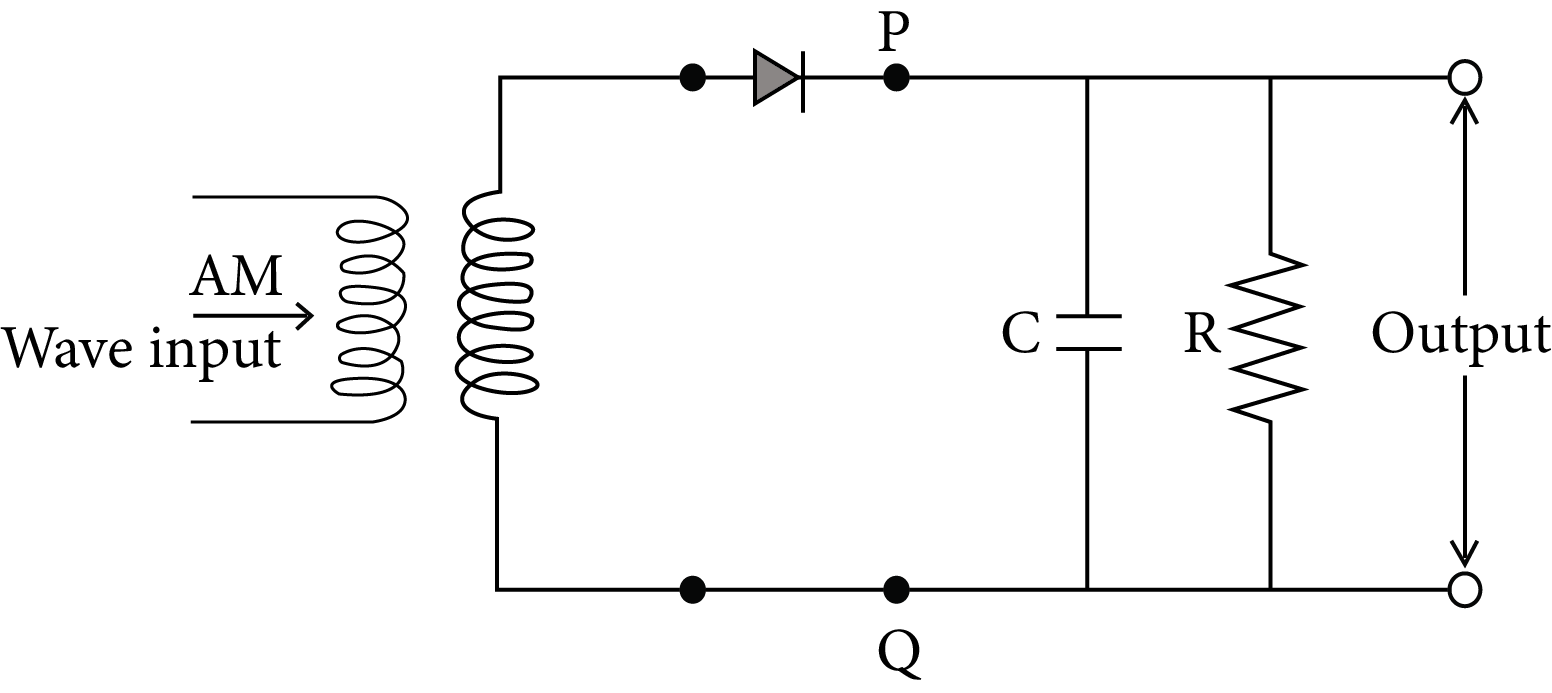
Simple Demodulator Circuit
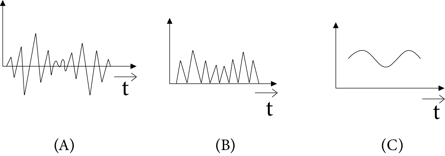
Simple Demodulator Waveform
Mobile Telephony
When we look around, we may observe many individuals conversing on cell phones or mobile phones in marketplaces, on trains and buses, and as they cross streets. The way we interact and live has changed thanks to mobile phones. The appearance and functionality of mobile phones have changed along with technological innovation. In addition to making and receiving phone calls, the newest mobile phones also allow users to:
Store contact information
Make task or to-do lists
Keep track of appointments and set reminders
Use the built- in calculator for simple maths.
Send or receive email
Get information (news, entertainment, stock quotes) from the Internet
Play games
Listen radio/music and watch TV
Send text messages
Take photos and videos etc.
Formula Chart:
Surface wave propagation: $E_{S}=\frac{E_{O}}{d} A$
Space wave propagation: $\epsilon=\epsilon_{0}\left[1-\frac{\mathrm{Nq}^{2}}{\epsilon_{0} m \omega^{2}}\right]$
Amplitude Modulation (AM):$m_{a}=\frac{K_{a} E_{m}}{E_{c}}$
Depth of Modulation: $m_{a}=\left[\frac{\text { Max. variation in amplitude of carrier }}{\text { from its unmodulated value }}\right] \times 100 \%$
Lower frequency band of AM signal $=\left(\omega_{\mathrm{C}}-\omega_{\mathrm{m}}\right)$
Higher frequency band of AM signal $=\left(\omega_{C}+\omega_{m}\right)$
$(\text { Angular bandwidth })_{\mathrm{AM}}=\left(\omega \mathrm{c}+\omega_{\mathrm{m}}\right)-\left(\omega c-\omega_{\mathrm{m}}\right)=\left(2 \omega_{\mathrm{m}}\right)_{\max }$
$=\left(\frac{2 \omega_{m}}{2 \pi}\right)_{\max }=\left(2 f_{m}\right)_{\max }$
Example 1: An antenna is mounted on a $400 \mathrm{~m}$ tall building. What will be the wavelength of signal that can be radiated effectively by the transmission tower upto a range of $44 \mathrm{~km}$ ?
$37.8 \mathrm{~m}$
$605 \mathrm{~m}$
$75.6 \mathrm{~m}$
$302 \mathrm{~m}$
Answer: A,C,D
Explanation
h : height of antenna
$\lambda$ : wavelength of signal
$\mathrm{h}<\lambda$
$\lambda>\mathrm{h}$
$\lambda>400 \mathrm{~m}$
Example 2: A transmitting antenna at top of a tower has a height of $50 \mathrm{~m}$ and the height of the receiving antenna is $80 \mathrm{~m}$. What is the range of communication for Line of Sight (LoS) mode?
[use radius of earth $=6400 \mathrm{~km}$ ]
$45.5 \mathrm{~km}$
$80.2 \mathrm{~km}$
$144.1 \mathrm{~km}$
57.28 km
Answer: D
Explanation:
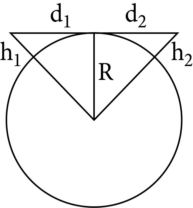
$d_{t}=\sqrt{2 R h_{1}}+\sqrt{2 R h_{2}}$
$=\sqrt{2 R}\left(\sqrt{h_{1}}+\sqrt{h_{2}}\right)$
$=\left(2 \times 6400 \times 10^{3}\right)^{1 / 2}(\sqrt{50}+\sqrt{80})$
$=3578(7.07+8.94)$
$=57.28 \mathrm{~km}$
Common Errors or Mistakes that Should be Avoided by the Students Keeping the Exam Point of View:
Students forget to write the working formula and not read definitions properly.
The answers should be by the marks allotted. For example, a question of 2 marks should not be answered in a whole page. Students should stick to the important points to gain full marks in the question. This will also help to have sufficient time to complete the paper.
Sometimes, even good students forget to write down the formula when working on numerical. Students should note that few marks are allotted for the formula and this will result in not scoring the full mark for the numerical.
Students should learn the formula thoroughly to avoid confusion in the examination. Often students get confused and flip the numerator and denominator in the formulae. This results in the entire numerical to be incorrect and no marks are awarded for the answer.
For diagram questions, it is a must that students label the diagram. To make the paper more presentable, students should mark these labels in a pencil or with a different colour pen.
1 mark questions that ask for “Yes” or “No” answers should be written along with its reason to achieve full marks in this question. ½ mark is allotted for each part.
In the exam, most of the questions have parts in it. Each part is allotted a specific mark and often students overlook these small parts asked and results in losing marks in the question, either ½ a mark or 3 marks for the same.
Students should avoid making question mistakes in the answer they are writing. Marks will not be allotted for incorrect question numbers.
When a student wants to rewrite a certain question that has already been answered, they must make sure that the incorrect answer is struck out. If a student fails to strike out the incorrect answer, as per the CBSE guidelines, the examiner will take the first attempt as the answer to the question and ignore the second.
Importance of Communication System
This chapter focuses on explaining the principles of communication systems used across the world. It explains how information is interpreted by a complex system of electronics such as a transmitter, channel, and receiver.
A signal is developed by the transmitter to send information to a receiver located at a distance. The distance can be quite far. It all depends on the strength of the bandwidth of a communication system sending messages.
In this chapter, students will learn the different types of communication systems used to send information according to the differences in the bandwidth of the radio signals sent. These signals are measured using the units of the frequency.
On proceeding further, it will explain what sky-wave propagation is and what critical frequency stands for. The mathematical expressions of all these terms will explain how we calculate and calibrate them to maintain a relentless communication channel. The use of Communication System notes for JEE Advanced will simplify the concepts so that the aspirants can understand them faster.
This chapter will also explain what remote sensing is and how we can modulate radio waves. The concept of developing a communication channel solely depends on radio waves sent across the world.
Benefits of Vedantu’s Communication System Notes for JEE Advanced
These revision notes have been prepared for this chapter to provide a simpler version of all the concepts and scientific principles involved in a communication system.
This chapter is taught to teach students how we communicate using electronic devices. Hence, these new concepts will need an easier explanation to prepare. These notes will enable you to understand these principles faster and guide you to complete revising this chapter.
These notes come with sample questions to test your preparation level. Once you are done preparing this chapter, you can check your level of understanding by answering these questions. Find out how the experts have solved them to strengthen your answering skills.
Resolve doubts on your own using Communication System Class 12 notes and reduce your preparation time considerably.
Download Free Communication System Notes PDF
These revision notes will be the best study material you can have for free to complete studying this chapter. Revise this chapter in no time and use the easier format to remember the crucial concepts of communication systems. You can download and use this file according to your study sessions to add more convenience.
Important Related Links for NEET

FAQs on Revision Notes on Communication Systems for NEET 2026
1. What is a digital signal?
A signal where the voltage or current has only two values is termed a digital signal.
2. What is an analogue signal?
An analogue signal can be defined as a signal that can change or modulate its magnitude of voltage or current relentlessly in accordance with time.
3. What is the transmission of signals?
The process of converting information into signals and sending them to a distant receiver is called the transmission of signals. It is done by using a transmitter. On the other end, a receiver receives the signals sent by a transmitter.
4. What do you mean by a communication channel?
According to the concepts of the communication systems, a channel or a path is set between a sender and a receiver for exchanging information. This channel is set by a system that can interpret information into radio signals and can transmit it using a transmitter and received by a receiver. This is called a communication channel.