


Two straight infinitely long and thin parallel wires are spaced $0.1{\text{m}}$ apart and carry a current of $10{\text{A}}$ each. Find the magnetic field at a point at a distance of $0.1{\text{m}}$ from both the wires in the two cases when the currents are in the:
1) Same direction,
2) Opposite direction
Answer
271.5k+ views
Hint: The direction of the magnetic field at some point due to a current-carrying wire will always be perpendicular to the direction of the current in the wire. Here the magnitude of the magnetic field due to each parallel wire at the given point will be the same but will have different directions. So to obtain the net magnetic field at the given point we have to resolve the magnetic fields due to each wire into their respective components.
Formula used:
The magnetic field at a point due to an infinitely long current-carrying wire is given by, $B = \dfrac{{{\mu _0}I}}{{2\pi d}}$ where ${\mu _0}$ is the permeability of free space, $I$ is the current in the wire and $d$ is the distance between the wire and the point.
Complete step by step answer:
Step 1: Sketch a figure representing the arrangement of the two wires and the point at which the magnetic field is to be determined. Also, list the given parameters.
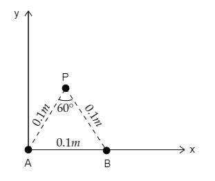
In the above figure, the two wires are considered to be placed so that they pass through the plane of the paper and points A and B represent any point of along the length of the two wires. P is the point at which the magnetic field due to the current in the two the wires is to be determined.
The current through each wire is given to be $I = 10{\text{A}}$ .
The distance between the two wires is given to be $AB = 0.1{\text{m}}$ .
The distance between point P and each wire is given to be $AP = AP = d = 0.1{\text{m}}$.
Since the triangle APB forms an equilateral triangle of side $0.1{\text{m}}$, the angle subtended at P will be $\angle P = 60^\circ $.
Step 2: Express the magnetic field at P due to each wire.
The magnetic field at point P due to wire A or wire B is equal in magnitude and so it can be expressed as ${B_A} = {B_B} = B = \dfrac{{{\mu _0}I}}{{2\pi d}}$ ---------- (1)
Substituting for $I = 10{\text{A}}$, $d = 0.1{\text{m}}$ and ${\mu _0} = 4\pi \times {10^{ - 7}}{\text{Tm}}{{\text{A}}^{ - 1}}$ in equation (1) we get, $B = \dfrac{{4\pi \times {{10}^{ - 7}} \times 10}}{{2\pi \times 0.1}} = 2 \times {10^{ - 5}}{\text{T}}$
Thus the magnetic field at P due to each individual wire will be $B = 2 \times {10^{ - 5}}{\text{T}}$ .
Step 3: Take the direction of the current in the two wires to be the same and obtain the net magnetic field at P.
Case 1: Current is in the same direction in both wires
Let the direction of the current in both wires be out of the plane. Then by right-hand thumb rule, the direction of the magnetic field will be anticlockwise and at P the magnetic field due to each wire will have the directions given below.
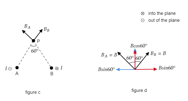
If we resolve the magnetic fields at P due to each wire into horizontal and vertical components as shown in figure b, then only their horizontal components prevail.
So the net magnetic field at P will be ${B_{net}} = 2B\sin 60^\circ $ -------- (2)
Substituting for $B = 2 \times {10^{ - 5}}{\text{T}}$ and $\sin 60^\circ = \dfrac{{\sqrt 3 }}{2}$ in equation (2) we get, ${B_{net}} = 2 \times 2 \times {10^{ - 5}} \times \dfrac{{\sqrt 3 }}{2} = 2\sqrt 3 \times {10^{ - 5}}{\text{T}}$
$\therefore $ the net magnetic field at P when current is in the same direction in the two wires is ${B_{net}} = 2\sqrt 3 \times {10^{ - 5}}{\text{T}}$ .
Step 4: Take the direction of the current in the two wires to be the opposite and obtain the net magnetic field at P.
Case 1: Current is in the opposite direction in the two wires
Let the direction of the current in wire A be out of the plane and that in B be into the plane. Then by right-hand thumb rule, the direction of the magnetic field due to wire A will be anticlockwise while the direction of the magnetic field due to wire B will be clockwise. At P the magnetic field due to each wire will have the directions given below.
If we resolve the magnetic fields at P due to each wire into horizontal and vertical components as shown in figure d, then only their vertical components prevail.
So the net magnetic field at P will be ${B_{net}} = 2B\cos 60^\circ $ -------- (3)
Substituting for $B = 2 \times {10^{ - 5}}{\text{T}}$ and $\cos 60^\circ = \dfrac{1}{2}$ in equation (3) we get, ${B_{net}} = 2 \times 2 \times {10^{ - 5}} \times \dfrac{1}{2} = 2 \times {10^{ - 5}}{\text{T}}$
$\therefore $ The net magnetic field at P when current is in the opposite direction in the two wires is ${B_{net}} = 2 \times {10^{ - 5}}{\text{T}}$.
Note: According to the right-hand thumb rule, the right thumb indicates the direction of the current in the wire and the direction in which the remaining fingers curl around the thumb indicates the direction of the magnetic field. While resolving the components of the magnetic field at P, the vertical component will be the cosine component and the horizontal component will be the sine component. The net magnetic field in the first case will be along the negative x-direction and the net magnetic field in the second case will be along the positive y-direction.
Formula used:
The magnetic field at a point due to an infinitely long current-carrying wire is given by, $B = \dfrac{{{\mu _0}I}}{{2\pi d}}$ where ${\mu _0}$ is the permeability of free space, $I$ is the current in the wire and $d$ is the distance between the wire and the point.
Complete step by step answer:
Step 1: Sketch a figure representing the arrangement of the two wires and the point at which the magnetic field is to be determined. Also, list the given parameters.
In the above figure, the two wires are considered to be placed so that they pass through the plane of the paper and points A and B represent any point of along the length of the two wires. P is the point at which the magnetic field due to the current in the two the wires is to be determined.
The current through each wire is given to be $I = 10{\text{A}}$ .
The distance between the two wires is given to be $AB = 0.1{\text{m}}$ .
The distance between point P and each wire is given to be $AP = AP = d = 0.1{\text{m}}$.
Since the triangle APB forms an equilateral triangle of side $0.1{\text{m}}$, the angle subtended at P will be $\angle P = 60^\circ $.
Step 2: Express the magnetic field at P due to each wire.
The magnetic field at point P due to wire A or wire B is equal in magnitude and so it can be expressed as ${B_A} = {B_B} = B = \dfrac{{{\mu _0}I}}{{2\pi d}}$ ---------- (1)
Substituting for $I = 10{\text{A}}$, $d = 0.1{\text{m}}$ and ${\mu _0} = 4\pi \times {10^{ - 7}}{\text{Tm}}{{\text{A}}^{ - 1}}$ in equation (1) we get, $B = \dfrac{{4\pi \times {{10}^{ - 7}} \times 10}}{{2\pi \times 0.1}} = 2 \times {10^{ - 5}}{\text{T}}$
Thus the magnetic field at P due to each individual wire will be $B = 2 \times {10^{ - 5}}{\text{T}}$ .
Step 3: Take the direction of the current in the two wires to be the same and obtain the net magnetic field at P.
Case 1: Current is in the same direction in both wires
Let the direction of the current in both wires be out of the plane. Then by right-hand thumb rule, the direction of the magnetic field will be anticlockwise and at P the magnetic field due to each wire will have the directions given below.
If we resolve the magnetic fields at P due to each wire into horizontal and vertical components as shown in figure b, then only their horizontal components prevail.
So the net magnetic field at P will be ${B_{net}} = 2B\sin 60^\circ $ -------- (2)
Substituting for $B = 2 \times {10^{ - 5}}{\text{T}}$ and $\sin 60^\circ = \dfrac{{\sqrt 3 }}{2}$ in equation (2) we get, ${B_{net}} = 2 \times 2 \times {10^{ - 5}} \times \dfrac{{\sqrt 3 }}{2} = 2\sqrt 3 \times {10^{ - 5}}{\text{T}}$
$\therefore $ the net magnetic field at P when current is in the same direction in the two wires is ${B_{net}} = 2\sqrt 3 \times {10^{ - 5}}{\text{T}}$ .
Step 4: Take the direction of the current in the two wires to be the opposite and obtain the net magnetic field at P.
Case 1: Current is in the opposite direction in the two wires
Let the direction of the current in wire A be out of the plane and that in B be into the plane. Then by right-hand thumb rule, the direction of the magnetic field due to wire A will be anticlockwise while the direction of the magnetic field due to wire B will be clockwise. At P the magnetic field due to each wire will have the directions given below.
If we resolve the magnetic fields at P due to each wire into horizontal and vertical components as shown in figure d, then only their vertical components prevail.
So the net magnetic field at P will be ${B_{net}} = 2B\cos 60^\circ $ -------- (3)
Substituting for $B = 2 \times {10^{ - 5}}{\text{T}}$ and $\cos 60^\circ = \dfrac{1}{2}$ in equation (3) we get, ${B_{net}} = 2 \times 2 \times {10^{ - 5}} \times \dfrac{1}{2} = 2 \times {10^{ - 5}}{\text{T}}$
$\therefore $ The net magnetic field at P when current is in the opposite direction in the two wires is ${B_{net}} = 2 \times {10^{ - 5}}{\text{T}}$.
Note: According to the right-hand thumb rule, the right thumb indicates the direction of the current in the wire and the direction in which the remaining fingers curl around the thumb indicates the direction of the magnetic field. While resolving the components of the magnetic field at P, the vertical component will be the cosine component and the horizontal component will be the sine component. The net magnetic field in the first case will be along the negative x-direction and the net magnetic field in the second case will be along the positive y-direction.
Recently Updated Pages
JoSAA Counselling 2026: JoSAA 2026 Mock Seat Allotment LIVE: Round 2 Result Released, Registration, Choice Filling and Ranks
Circuit Switching vs Packet Switching: Key Differences Explained
JEE General Topics in Chemistry Important Concepts and Tips
JEE Extractive Metallurgy Important Concepts and Tips for Exam Preparation
JEE Atomic Structure and Chemical Bonding important Concepts and Tips
JEE Amino Acids and Peptides Important Concepts and Tips for Exam Preparation
Trending doubts
JEE Main 2026: Exam Dates, Session 2 Updates, City Slip, Admit Card & Latest News
JEE Main Participating Colleges 2026 - A Complete List of Top Colleges
Kinematics Mock Test for JEE Main 2025-26: Comprehensive Practice
Understanding the Electric Field of a Uniformly Charged Ring
Understanding Atomic Structure for Beginners
Derivation of Equation of Trajectory Explained for Students
Other Pages
CBSE Class 12 Physics Question Paper 2026: Download SET-wise PDF with Answer Key & Analysis
JEE Advanced 2026 Notification Out with Exam Date, Registration (Extended), Syllabus and More
JEE Advanced Percentile vs Marks 2026: JEE Main Cutoff, AIR & IIT Admission Guide
JEE Advanced Weightage Chapter Wise 2026 for Physics, Chemistry, and Mathematics
JEE Main Marking Scheme 2026- Paper-Wise Marks Distribution and Negative Marking Details
Kinematics Mock Test for JEE Main 2025-26: Practice & Ace the Exam