


Two resistors 400 Ω and 800 Ω are connected in series across a 6 V battery. The potential difference measured by a voltmeter of 10 k Ω across 400 Ω resistors is close to:
A. 2.05 V
B. 2 V
C. 1.95 V
D. 1.8 V
Answer
274.8k+ views
Hint:In the series combination of resistance, the current is same for each resistor. A resistor is known to be connected in series if same amount of current flows through the resistors. We can determine the potential difference of the circuit by using ohm’s law.
Formula used
By ohm’s law,
$V=IR$
Where V is voltage, I is current and R is resistance.
Resistors in series,
\[\begin{array}{l}{R_s} = {R_1} + {R_2}....\\{\rm{ }}\end{array}\]
Resistors in series,
\[\dfrac{1}{{{R_p}}} = \dfrac{1}{{{R_1}}} + \dfrac{1}{{{R_2}}}....\]
Complete step by step solution:
To calculate the effective resistance of the circuit as:
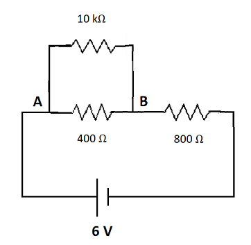
Image:Circuit diagram
As 400 Ω and 10 k Ω are connected in parallel, thus resistance along AB will be,
Let \[{R_1} = 400\Omega \] and \[{R_2} = 10k\Omega = 1000\Omega \] are two resistance connected in parallel as shown in figure, then by using formula of parallel combination of resistance,
\[\dfrac{1}{{{R_p}}} = \dfrac{1}{{{R_1}}} + \dfrac{1}{{{R_2}}}\\ \Rightarrow \dfrac{1}{{{R_p}}} {\rm{ = }}\dfrac{1}{{400}} + \dfrac{1}{{1000}}\\ \Rightarrow \dfrac{1}{{{R_p}}} {\rm{ = }}\dfrac{{400 \times 1000}}{{400 + 1000}}\\ \Rightarrow {\rm{ }}{{\rm{R}}_p}{\rm{ = }}\dfrac{{5000}}{{13}}\Omega \]
Now this resistance is connected with the given resistance \[{R_3} = \] 800 Ω as shown in figure, then by using formula of series combination of resistance,
\[{R_s} = {R_p} + {R_3}\\ \Rightarrow {R_s}{\rm{ = }}\dfrac{{5000}}{{13}} + 800\\ \Rightarrow {R_s}{\rm{ = }}\dfrac{{15400}}{{13}}\Omega \]
To find current after connecting a battery of 6 V,
As, \[I = \dfrac{V}{R} = \dfrac{6}{{\dfrac{{15400}}{{13}}}}\]
\[I= \dfrac{{39}}{{7700}}A\]
As we know
\[V = IR\\ \Rightarrow V{\rm{ = }}\dfrac{{39}}{{7700}} \times \dfrac{{5000}}{{13}}\\ \therefore V{\rm{ = 1}}{\rm{.95 V}}\]
Therefore the potential difference measured by a voltmeter of 10 k Ω across 400 Ω resistors is close to 1.95 V.
Hence, option C is the correct answer
Note:A resistor is defined as a passive two terminal electrical component that implements electrical resistance as a circuit element. It reduces the flow of current and lower voltage levels within the circuits.
Formula used
By ohm’s law,
$V=IR$
Where V is voltage, I is current and R is resistance.
Resistors in series,
\[\begin{array}{l}{R_s} = {R_1} + {R_2}....\\{\rm{ }}\end{array}\]
Resistors in series,
\[\dfrac{1}{{{R_p}}} = \dfrac{1}{{{R_1}}} + \dfrac{1}{{{R_2}}}....\]
Complete step by step solution:
To calculate the effective resistance of the circuit as:
Image:Circuit diagram
As 400 Ω and 10 k Ω are connected in parallel, thus resistance along AB will be,
Let \[{R_1} = 400\Omega \] and \[{R_2} = 10k\Omega = 1000\Omega \] are two resistance connected in parallel as shown in figure, then by using formula of parallel combination of resistance,
\[\dfrac{1}{{{R_p}}} = \dfrac{1}{{{R_1}}} + \dfrac{1}{{{R_2}}}\\ \Rightarrow \dfrac{1}{{{R_p}}} {\rm{ = }}\dfrac{1}{{400}} + \dfrac{1}{{1000}}\\ \Rightarrow \dfrac{1}{{{R_p}}} {\rm{ = }}\dfrac{{400 \times 1000}}{{400 + 1000}}\\ \Rightarrow {\rm{ }}{{\rm{R}}_p}{\rm{ = }}\dfrac{{5000}}{{13}}\Omega \]
Now this resistance is connected with the given resistance \[{R_3} = \] 800 Ω as shown in figure, then by using formula of series combination of resistance,
\[{R_s} = {R_p} + {R_3}\\ \Rightarrow {R_s}{\rm{ = }}\dfrac{{5000}}{{13}} + 800\\ \Rightarrow {R_s}{\rm{ = }}\dfrac{{15400}}{{13}}\Omega \]
To find current after connecting a battery of 6 V,
As, \[I = \dfrac{V}{R} = \dfrac{6}{{\dfrac{{15400}}{{13}}}}\]
\[I= \dfrac{{39}}{{7700}}A\]
As we know
\[V = IR\\ \Rightarrow V{\rm{ = }}\dfrac{{39}}{{7700}} \times \dfrac{{5000}}{{13}}\\ \therefore V{\rm{ = 1}}{\rm{.95 V}}\]
Therefore the potential difference measured by a voltmeter of 10 k Ω across 400 Ω resistors is close to 1.95 V.
Hence, option C is the correct answer
Note:A resistor is defined as a passive two terminal electrical component that implements electrical resistance as a circuit element. It reduces the flow of current and lower voltage levels within the circuits.
Recently Updated Pages
Wheatstone Bridge – Principle, Formula, Diagram & Applications
Mass vs Weight: Key Differences Explained for Students
Circuit Switching vs Packet Switching: Key Differences Explained
Uniform Acceleration Explained: Formula, Examples & Graphs
Young’s Double Slit Experiment Derivation Explained
Classification of Drugs in Chemistry: Types, Examples & Exam Guide
Trending doubts
JEE Main 2026: Exam Dates, Session 2 Updates, City Slip, Admit Card & Latest News
Understanding the Electric Field of a Uniformly Charged Ring
Understanding Atomic Structure for Beginners
Derivation of Equation of Trajectory Explained for Students
Electron Gain Enthalpy and Electron Affinity Explained
How to Convert a Galvanometer into an Ammeter or Voltmeter
Other Pages
CBSE Class 12 Physics Question Paper 2026: Download SET-wise PDF with Answer Key & Analysis
JEE Advanced 2026 Notification Out with Exam Date, Registration (Extended), Syllabus and More
JEE Advanced Percentile vs Marks 2026: JEE Main Cutoff, AIR & IIT Admission Guide
JEE Advanced Weightage Chapter Wise 2026 for Physics, Chemistry, and Mathematics
Understanding Electromagnetic Waves and Their Importance
Understanding Combined Translation and Rotational Motion