


There is an inductor of $5\,mH$. Current flowing through the inductor at any instant of time is given by the relation.
$I = {t^2} + 4$
If, is in ampere and $'t'$ in sec, find out
(i) Emf induced in the inductor at $t = 1$ and $t = 3\,s$ .
(ii) Plot $ E \,v/s\,t$ graph.
Answer
267.3k+ views
Hint: Use the formula of the emf given below and substitute the value of the induction and the equation of the current. Differentiate the current equation, and substitute the value of the time taken in it to find the emf at that corresponding time. The emf is directly proportional to time taken.
Useful formula:
The formula of the emf is given by
$ E = L\dfrac{{di}}{{dt}}$
Where $ E $ is the emf of the inductor, $L$ is the induction and $i$ is the current flowing through the inductor circuit.
Complete step by step solution:
It is given that the
The inductance of the inductor, \[L = 5\,mH = 5 \times {10^{ - 3}}\,H\]
The current through the inductor at time, $i = {t^2} + 4$
(i) Let us calculate the value of the emf through the inductor at $t = 1$ . First, write the formula of the emf,
$ E = L\dfrac{{di}}{{dt}}$
Substitute the known values in the above step,
$ E = 5 \times {10^{ - 3}} \times \dfrac{{d\left( {{t^2} + 4} \right)}}{{dt}}$
By performing differentiation in the above step,
$ E = 5 \times {10^{ - 3}} \times 2t$ -----(1)
Substituting the value of $t$ as $1\,{\text{second}}$ ,
$ E = 0.01\,V$
Let us calculate the emf for $t = 3\,s$ ,by substituting the value of $t$ as $3\,{\text{second}}$ ,
$ E = 5 \times {10^{ - 3}} \times 2 \times 3$
$ E = 30 \times {10^{ - 3}}$
$ E = 0.3\,V$
Hence the emf of the inductor is obtained as $0.01\,V$ for $1\,\operatorname{s} $ time and $0.3\,V$ for the time period of $3\,s$ .
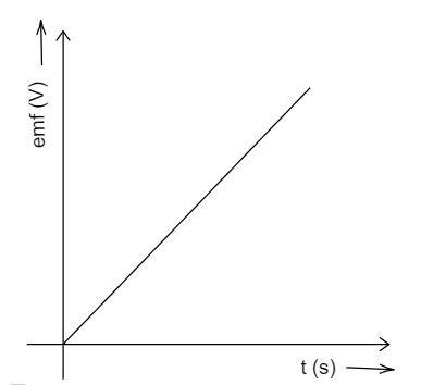
(ii) The below graph shows the relation between the emf and the time taken for the current to flow. The emf is directly proportional to the current and thus the graph is straight line.
Note: The inductors can be functioned in two ways, first is to control signals and in the other is to store electrical energy. In the factor that helps to produce the emf, also generate the reactive fluxes that act against the produced emf.
Useful formula:
The formula of the emf is given by
$ E = L\dfrac{{di}}{{dt}}$
Where $ E $ is the emf of the inductor, $L$ is the induction and $i$ is the current flowing through the inductor circuit.
Complete step by step solution:
It is given that the
The inductance of the inductor, \[L = 5\,mH = 5 \times {10^{ - 3}}\,H\]
The current through the inductor at time, $i = {t^2} + 4$
(i) Let us calculate the value of the emf through the inductor at $t = 1$ . First, write the formula of the emf,
$ E = L\dfrac{{di}}{{dt}}$
Substitute the known values in the above step,
$ E = 5 \times {10^{ - 3}} \times \dfrac{{d\left( {{t^2} + 4} \right)}}{{dt}}$
By performing differentiation in the above step,
$ E = 5 \times {10^{ - 3}} \times 2t$ -----(1)
Substituting the value of $t$ as $1\,{\text{second}}$ ,
$ E = 0.01\,V$
Let us calculate the emf for $t = 3\,s$ ,by substituting the value of $t$ as $3\,{\text{second}}$ ,
$ E = 5 \times {10^{ - 3}} \times 2 \times 3$
$ E = 30 \times {10^{ - 3}}$
$ E = 0.3\,V$
Hence the emf of the inductor is obtained as $0.01\,V$ for $1\,\operatorname{s} $ time and $0.3\,V$ for the time period of $3\,s$ .
(ii) The below graph shows the relation between the emf and the time taken for the current to flow. The emf is directly proportional to the current and thus the graph is straight line.
Note: The inductors can be functioned in two ways, first is to control signals and in the other is to store electrical energy. In the factor that helps to produce the emf, also generate the reactive fluxes that act against the produced emf.
Recently Updated Pages
States of Matter Chapter For JEE Main Chemistry
Young’s Double Slit Experiment Derivation Explained
Wheatstone Bridge – Principle, Formula, Diagram & Applications
Circuit Switching vs Packet Switching: Key Differences Explained
Mass vs Weight: Key Differences Explained for Students
[Awaiting the three content sources: Ask AI Response, Competitor 1 Content, and Competitor 2 Content. Please provide those to continue with the analysis and optimization.]
Trending doubts
JEE Main 2026: Exam Dates, Session 2 Updates, City Slip, Admit Card & Latest News
JEE Main Participating Colleges 2026 - A Complete List of Top Colleges
Kinematics Mock Test for JEE Main 2025-26: Comprehensive Practice
Kinematics Mock Test for JEE Main 2025-26: Practice & Ace the Exam
Hybridisation in Chemistry – Concept, Types & Applications
Understanding the Electric Field of a Uniformly Charged Ring
Other Pages
CBSE Class 12 Physics Question Paper 2026: Download SET-wise PDF with Answer Key & Analysis
JEE Advanced 2026 Notification Out with Exam Date, Registration (Extended), Syllabus and More
JEE Advanced Percentile vs Marks 2026: JEE Main Cutoff, AIR & IIT Admission Guide
JEE Advanced 2026 Marks vs Rank: Estimate IIT Rank from Your Score
JEE Advanced Weightage Chapter Wise 2026 for Physics, Chemistry, and Mathematics
Derivation of Equation of Trajectory Explained for Students