


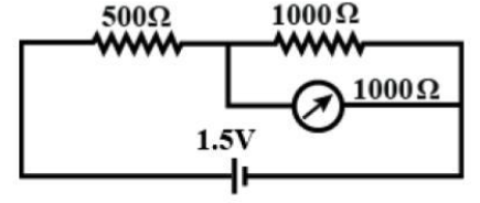
The resistance 500$\Omega $ and 1000$\Omega$ are connected in series with a battery of 1.5 volts. The voltage across the 1000 ohm resistance is measured by a voltmeter having a resistance of 1000 $\Omega $. The reading in the voltmeter would be:
A) 1.5 volt
B) 1.0 volt
C) 0.75 volt
D) 0.5 volt
Answer
258.6k+ views
Hint: A voltmeter is an instrument used for measuring potential difference or voltage levels between any two points in a circuit when connected in parallel to the portion of the circuit for which the voltage is to be measured. Voltmeters can be used for measuring voltage drop. Voltage is always measured across or in parallel to the circuits.
Complete step by step solution:
Let I be the total current flowing in the circuit which subsequently gets divided into I’ flows through both the resistance of 1000 ohm and the voltmeter, as shown in the following figure.
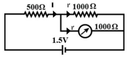
As the voltmeter and the resistance of 1000 ohm are in parallel and both of them have a resistance of equal magnitude, so the current will be equally distributed among them. Hence, we can say that,
$I' = \dfrac{I}{2}$ …………… (1)
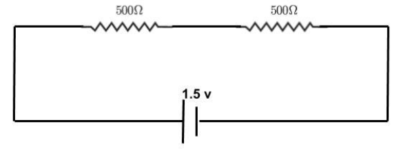
As there are two resistances in parallel each of which has a magnitude of 1000 ohms hence the equivalent resistance is given by,
${R_{eq}} = \dfrac{{1000 \times 1000}}{{1000 + 1000}}$
${R_{eq}} = 500\Omega $
The equivalent circuit is shown in the following circuit diagram.
The total current (I) flowing through the circuit is given by,
$I = \dfrac{V}{R}$
$ \Rightarrow I = \dfrac{{1.5}}{{500 + 500}}$
$ \Rightarrow I = 1.5 \times {10^{ - 3}}A$
Now from equation (1) current I’ is given by,
$I' = \dfrac{{1.5 \times {{10}^{ - 3}}}}{2}$
$ \Rightarrow I' = 0.75 \times {10^{ - 3}}A$
We know that the voltmeter reading (VR) can be obtained by multiplying the current flowing through it and its own resistance. Mathematically it is given by,
${V_R} = I' \times 1000\Omega $
$\therefore {V_R} = 0.75V$
Since the reading on the voltmeter is found to be 0.75 volts hence we can say that option C is the current answer.
Note: We have already discussed the voltmeter in the above section. A voltmeter is an important measuring device in electrical measurements but there is another important device known as ammeter which needs to be mentioned here. An ammeter is a device which measures the current flowing in a circuit. An ammeter is connected in parallel to the part of the circuit whose current is to be measured.
Complete step by step solution:
Let I be the total current flowing in the circuit which subsequently gets divided into I’ flows through both the resistance of 1000 ohm and the voltmeter, as shown in the following figure.
As the voltmeter and the resistance of 1000 ohm are in parallel and both of them have a resistance of equal magnitude, so the current will be equally distributed among them. Hence, we can say that,
$I' = \dfrac{I}{2}$ …………… (1)
As there are two resistances in parallel each of which has a magnitude of 1000 ohms hence the equivalent resistance is given by,
${R_{eq}} = \dfrac{{1000 \times 1000}}{{1000 + 1000}}$
${R_{eq}} = 500\Omega $
The equivalent circuit is shown in the following circuit diagram.
The total current (I) flowing through the circuit is given by,
$I = \dfrac{V}{R}$
$ \Rightarrow I = \dfrac{{1.5}}{{500 + 500}}$
$ \Rightarrow I = 1.5 \times {10^{ - 3}}A$
Now from equation (1) current I’ is given by,
$I' = \dfrac{{1.5 \times {{10}^{ - 3}}}}{2}$
$ \Rightarrow I' = 0.75 \times {10^{ - 3}}A$
We know that the voltmeter reading (VR) can be obtained by multiplying the current flowing through it and its own resistance. Mathematically it is given by,
${V_R} = I' \times 1000\Omega $
$\therefore {V_R} = 0.75V$
Since the reading on the voltmeter is found to be 0.75 volts hence we can say that option C is the current answer.
Note: We have already discussed the voltmeter in the above section. A voltmeter is an important measuring device in electrical measurements but there is another important device known as ammeter which needs to be mentioned here. An ammeter is a device which measures the current flowing in a circuit. An ammeter is connected in parallel to the part of the circuit whose current is to be measured.
Recently Updated Pages
JEE Main Mock Test 2025-26: Electromagnetic Induction & Alternating Currents
JEE Main Mock Test 2025-26: Optics Chapter Practice Online
JEE Main 2025-26 Mock Test: Properties of Solids and Liquids
JEE Main Mock Test 2025-26: Dual Nature of Matter & Radiation
JEE Main 2025-26 Electromagnetic Waves Mock Test with Solutions
JEE Main 2025-26 Mock Test: Electronic Devices Chapter Practice
Trending doubts
JEE Main 2026: Exam Dates, Session 2 Updates, City Slip, Admit Card & Latest News
JEE Main Participating Colleges 2026 - A Complete List of Top Colleges
JEE Main Marking Scheme 2026- Paper-Wise Marks Distribution and Negative Marking Details
Hybridisation in Chemistry – Concept, Types & Applications
Understanding the Electric Field of a Uniformly Charged Ring
Derivation of Equation of Trajectory Explained for Students
Other Pages
CBSE Class 12 Physics Question Paper 2026: Download SET-wise PDF with Answer Key & Analysis
JEE Advanced 2026 - Exam Date (Released), Syllabus, Registration, Eligibility, Preparation, and More
JEE Advanced Marks vs Ranks 2025: Understanding Category-wise Qualifying Marks and Previous Year Cut-offs
JEE Advanced Weightage 2025 Chapter-Wise for Physics, Maths and Chemistry
Understanding Atomic Structure for Beginners
Understanding Electromagnetic Waves and Their Importance