


The following configuration of gate equivalent to:
A) NAND
B) XOR
C) OR
D) None of these
Answer
259.5k+ views
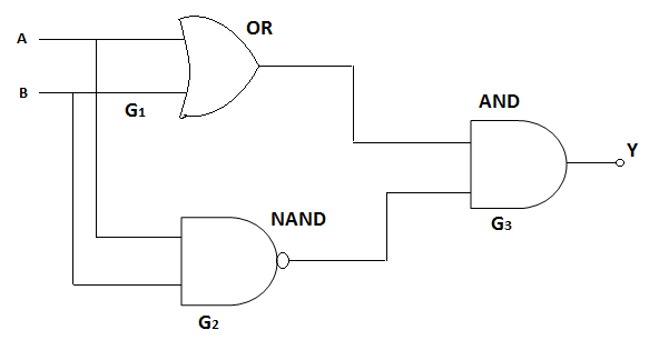
Hint: In the given configuration, the input is $A$ and $B$. So, the output will be $\left( {A + B} \right)$ for OR gate and $\left( {A.B} \right) = \overline A + \overline B $ for NAND gate. The resultant gate gives the high output signal when the number of high inputs is odd. Its output expression is $Y = A\overline B + B\overline A $.
Complete step by step answer:
In an OR gate, there are two or more input signals and like any other gate there is one output signal. This gate is called OR gate because if the first or the second or the third or …, i.e. if any of the input signals is high, the output signal will also be high.
In the given configuration, the input is $A$ and $B$. So, the output will be $\left( {A + B} \right)$
Joining the input of a NOT gate with the output of an AND gate, a NOT-AND, i.e., a NAND gate is constructed. So, the signal that comes at the output of an AND gate, goes to the input of a NOT gate. NOT gate inverts this signal and sends it to the output.
In the given configuration, the input is $A$ and $B$. So, the output will be $\left( {A.B} \right) = \overline A + \overline B $
In an AND gate, there are two or more input signals and any other gate there is one output signal. This gate is called AND gate because, if all the input signals, i.e., the first and the second and the third and … input signals are high, only then will the output voltage be high.
Here, the input is $\left( {A + B} \right)$ and $\left( {\overline A + \overline B } \right)$. So, the output will be $\left( {A + B} \right).\left( {\overline A + \overline B } \right)$
So, the given output is $Y = (A + B).(\overline A + \overline B )$ [DeMorgan’s theorem]
The above expression can also be rewritten as,
$Y = A\overline A + A\overline B + B\overline A + B\overline B $
$\implies Y = 0 + A\overline B + B\overline A + 0$
$\implies Y = A\overline B + B\overline A $
This is the expression of an XOR gate.
XOR gate is the digital logic gate that gives the high output signal when the number of high inputs is odd. XOR gate is also called the exclusive OR gate, because, if one, and only one of the inputs to the gate is high, the output result will also be high.
Note: DeMorgan’s theorem explains the identity between gates with inverted inputs and the gates with inverted outputs. In simple words, it states that the complement of the product of all the terms is equal to the sum of the complement of each term and vice versa. For example, a NAND gate is similar to a Negative-OR gate.
Recently Updated Pages
JEE Main Mock Test 2025-26: Electromagnetic Induction & Alternating Currents
JEE Main Mock Test 2025-26: Optics Chapter Practice Online
JEE Main 2025-26 Mock Test: Properties of Solids and Liquids
JEE Main Mock Test 2025-26: Dual Nature of Matter & Radiation
JEE Main 2025-26 Electromagnetic Waves Mock Test with Solutions
JEE Main 2025-26 Mock Test: Electronic Devices Chapter Practice
Trending doubts
JEE Main 2026: Exam Dates, Session 2 Updates, City Slip, Admit Card & Latest News
JEE Main Participating Colleges 2026 - A Complete List of Top Colleges
JEE Main Marking Scheme 2026- Paper-Wise Marks Distribution and Negative Marking Details
Hybridisation in Chemistry – Concept, Types & Applications
Understanding the Electric Field of a Uniformly Charged Ring
Derivation of Equation of Trajectory Explained for Students
Other Pages
CBSE Class 12 Physics Question Paper 2026: Download SET-wise PDF with Answer Key & Analysis
JEE Advanced 2026 - Exam Date (Released), Syllabus, Registration, Eligibility, Preparation, and More
JEE Advanced Marks vs Ranks 2025: Understanding Category-wise Qualifying Marks and Previous Year Cut-offs
JEE Advanced Weightage 2025 Chapter-Wise for Physics, Maths and Chemistry
Understanding Atomic Structure for Beginners
Understanding Electromagnetic Waves and Their Importance