


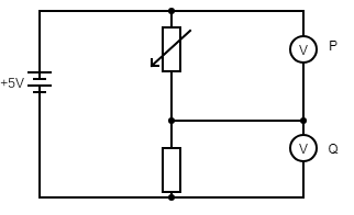
The diagram shows a potential divider circuit.
The resistance of the variable resistor is increased.
Which row shows what happens to the reading on voltmeter P and on voltmeter Q?
(A) Reading on Voltmeter P – decreases, reading on voltmeter Q-decreases
(B) Reading on Voltmeter P – decreases, reading on voltmeter Q-increases
(C) Reading on Voltmeter P – increases, reading on voltmeter Q-decreases
(D) Reading on Voltmeter P – increases, reading on voltmeter Q-increases
Answer
255.3k+ views
Hint: Note the circuit diagram carefully. Using ohm’s law, find the relation between voltage and resistance of the circuit. Voltmeter P is connected to the part of circuit majorly influenced by the variable resistor , whereas the voltage in Q is impacted by both the normal resistor and the variable resistor. Find the value changes using this logic.
Complete step by step solution:
It is given that the circuit is a potential divider circuit. It is a type of passive circuit which produces output voltage as a fraction of its input voltage. It is mainly implemented to distribute voltage across the circuit. Now let us assume in our given circuit, the emf of the circuit as E. The resistance in the variable resistor as r and the resistance in the fixed resistance as R.
Now, when the resistance of the variable resistor is increased, the voltmeter reading in the voltmeter P will increase, by virtue of ohm's law, which states that the potential difference across the circuit is directly proportional to the current flowing in the circuit.
\[V = Ir\]
Now, as r value increases, V value at P increases. Now, since the value of the other resistor is fixed, it will adjust itself so that the total voltmeter value is equal to that of the EMF of the circuit. Since voltmeter at P increases, the voltmeter at Q decreases to bring the overall value equal to that of EMF.
Hence, option (c) is the right answer for the given question.
Note: Terminal voltage is given as the potential difference that is observed across the terminals of the source battery. It is said that if the battery is not connected with the circuit, then the observed terminal voltage is equal to that of EMF of the battery. The voltmeter is used to measure the voltage across the circuit and can also be used to measure terminal voltage.
Recently Updated Pages
Mass vs Weight: Key Differences Explained for Students
Uniform Acceleration Explained: Formula, Examples & Graphs
JEE Main 2022 (June 25th Shift 2) Chemistry Question Paper with Answer Key
Average Atomic Mass - Important Concepts and Tips for JEE
JEE Main 2023 (April 15th Shift 1) Physics Question Paper with Answer Key
JEE Main 2022 (June 27th Shift 2) Chemistry Question Paper with Answer Key
Trending doubts
JEE Main 2026: Exam Dates, Session 2 Updates, City Slip, Admit Card & Latest News
JEE Main Marking Scheme 2026- Paper-Wise Marks Distribution and Negative Marking Details
JEE Main 2026 Application Login: Direct Link, Registration, Form Fill, and Steps
Hybridisation in Chemistry – Concept, Types & Applications
Understanding the Electric Field of a Uniformly Charged Ring
Derivation of Equation of Trajectory Explained for Students
Other Pages
CBSE Class 12 Physics Question Paper 2026: Download SET-wise PDF with Answer Key & Analysis
JEE Advanced 2026 - Exam Date (Released), Syllabus, Registration, Eligibility, Preparation, and More
JEE Advanced Marks vs Ranks 2025: Understanding Category-wise Qualifying Marks and Previous Year Cut-offs
JEE Advanced Weightage 2025 Chapter-Wise for Physics, Maths and Chemistry
Understanding Atomic Structure for Beginners
How to Convert a Galvanometer into an Ammeter or Voltmeter