

How Do Spherical and Parallel Plate Capacitors Compare in Structure and Function?
Capacitors play a crucial role in both JEE and NEET physics, especially when understanding different geometries enhances conceptual clarity.
What is a Capacitor? Real-Life Visualisation
A capacitor is like a temporary electrical storage tank, storing energy when connected and releasing it when needed. Picture charging your phone: the battery here acts like a capacitor, storing and releasing energy on demand.
Capacitors are vital in circuits that need controlled energy flow, such as camera flashes or filtering out unwanted AC in audio systems.
Understanding Capacitance and its Measurement
Capacitance quantifies how much charge a capacitor can store per volt. It uses the formula $C = \dfrac{Q}{V}$, where $Q$ is charge and $V$ is potential difference.
The SI unit of capacitance is the farad (F), but most practical capacitors are in microfarads due to the large value of 1 farad.
Parallel Plate Capacitor: Concept and Formula
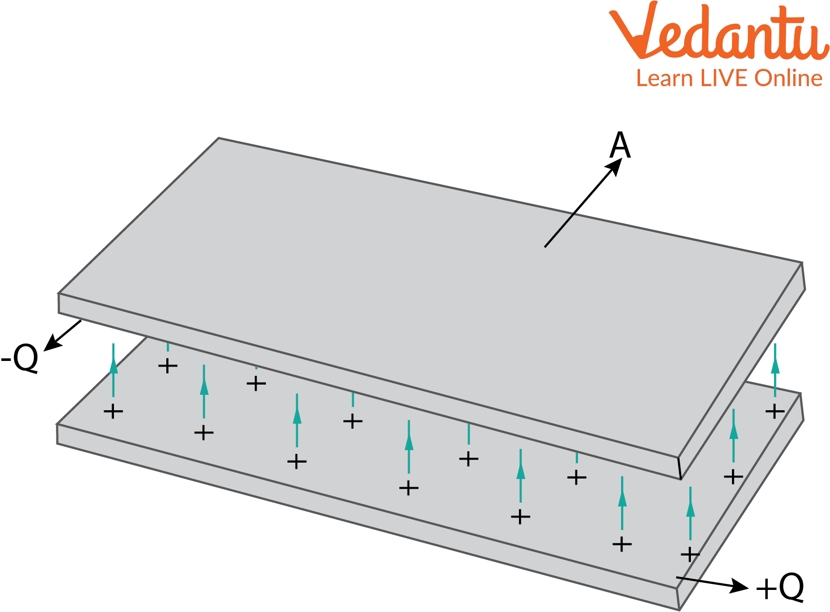
A parallel plate capacitor uses two flat conductive plates separated by a tiny gap. When connected to a battery, one plate gets positive charge, the other negative.

Uniform electric field forms between the plates. Capacitance depends on plate area $A$ and distance $d$:
$C = \dfrac{\varepsilon_0 A}{d}$
Here, $\varepsilon_0$ is vacuum permittivity. The electric field $E$ between plates is $E=\dfrac{V}{d}$.
For complex arrangements, refer to Understanding Equivalent Capacitance.
Visualisation: How Parallel Plate Capacitors Work
Visualise two closely spaced metal plates with invisible field lines going straight from one plate to the other. These lines represent energy being stored in the form of an electric field.
This field is uniform except at the edges, a fact crucial for theoretical and JEE problem-solving accuracy.
Spherical Capacitors: Structure and Explanation
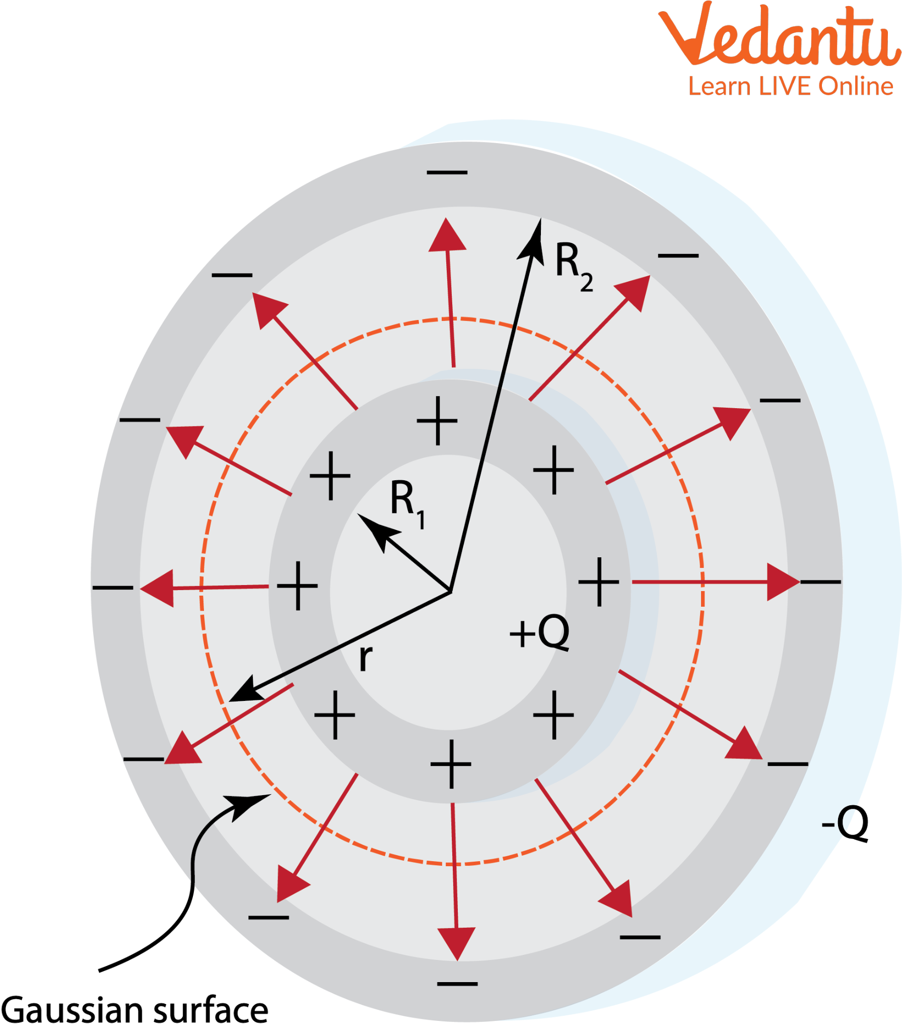
A spherical capacitor consists of two concentric spheres; the inner is charged positively, the outer negatively. The space between them stores energy.

The electric field exists only in the gap between the two shells. Using Gauss's Law, the field at distance $r$ (with $R_1
Potential difference $V$ between shells:
$V = \dfrac{Q}{4\pi\varepsilon_0} \left( \dfrac{1}{R_1} - \dfrac{1}{R_2} \right )$
So, capacitance of spherical capacitor:
$C = \dfrac{4\pi \varepsilon_0 R_1 R_2}{R_2 - R_1}$
Different dielectric materials placed in the gap modify capacitance, relevant for advanced JEE scenarios involving spherical capacitor with two dielectrics.
Explore charge sharing using Combination of Capacitors Explained.
Formula Summary Table: Parallel Plate vs. Spherical Capacitor
| Type | Capacitance Formula |
|---|---|
| Parallel Plate Capacitor | $C = \dfrac{\varepsilon_0 A}{d}$ |
| Spherical Capacitor | $C = \dfrac{4\pi\varepsilon_0 R_1 R_2}{R_2 - R_1}$ |
Other Capacitor Types: Brief Overview
- Parallel plate, spherical, and cylindrical capacitors are major types
- Variable capacitors allow tunable capacitance in circuits
- Ceramic and electrolytic capacitors are common in electronics
Cylindrical Capacitor: Quick Recap and Comparison
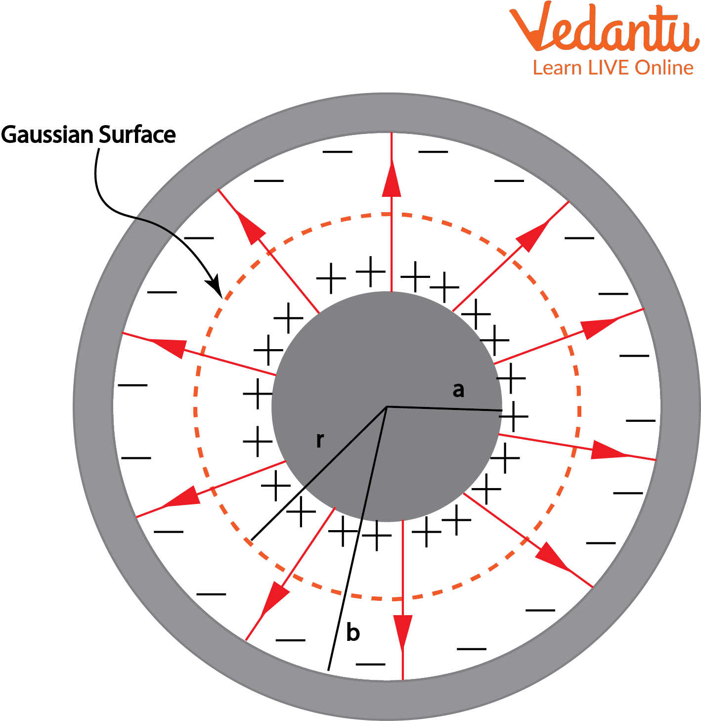
A cylindrical capacitor uses two coaxial cylinders, suitable for cable and underground transmission designs. Capacitance per unit length is:
$\dfrac{C}{L} = \dfrac{2\pi \varepsilon_0}{\ln (b/a)}$

Energy Stored in Capacitors: Fundamentals and Equations
Every capacitor stores energy in its electric field. The energy stored for any capacitor is given by:
$U = \dfrac{1}{2} C V^2 = \dfrac{1}{2} Q V = \dfrac{Q^2}{2C}$
This equation links stored charge, voltage, and capacitance, and it underpins many JEE conceptual and calculational problems.
Sample Problem: Capacitance of a Spherical Capacitor
Let $R_1 = 2\,\text{cm}$ and $R_2 = 5\,\text{cm}$ for a spherical capacitor in air. Calculate capacitance using the formula and take $\varepsilon_0=8.854 \times 10^{-12} \,\text{F/m}$.
$C = \dfrac{4\pi \varepsilon_0 R_1 R_2}{R_2 - R_1} = \dfrac{4\pi (8.854 \times 10^{-12})(0.02)(0.05)}{0.03}$, which gives approximately $3.7 \times 10^{-13}$ F.
Practice Question for JEE/NEET
A parallel plate capacitor has area $0.01\,\text{m}^2$ and separation $2\,\text{mm}$ in vacuum. Find its capacitance.
Comparative Insights: Parallel Plate vs. Spherical Capacitor
| Aspect | Parallel Plate Capacitor | Spherical Capacitor |
|---|---|---|
| Field Distribution | Uniform, between plates | Radial, between spheres |
| Edge Effects | Present, negligible in center | Not present |
| Capacitance Dependence | Area and gap | Radii of shells |
Key Applications of Capacitors
- Energy storage and smoothening voltage in circuits
- Signal coupling or filtering in electronics
- Tuning radios, TV, and oscillator circuits
- Power factor correction in AC circuits
Common Errors to Avoid (JEE/NEET)
- Overlooking units (F, $\mu$F, cm, m, etc.) in answers
- Assuming field is nonuniform in parallel plates' center
- Forgetting the role of dielectric in modifying capacitance
- Confusing formulas for different geometries
Capacitors in JEE and NEET Exams: Tips and Relevance
Capacitors often appear in numericals and conceptual MCQs. Focus on analyzing field distribution, correct formula applications, and energy calculations for maximum exam success.
Understanding field lines and Equipotential Surface in Capacitors is crucial for mastering potential-related questions.
For comparing with inductors, explore Difference Between Capacitor and Inductor for deeper understanding.
Related Topics To Explore
- Capacitor charging and discharging curves
- Electric potential and potential energy basics
- Dielectric breakdown and dielectric constant
- Series and parallel combinations of capacitors
- Electrostatics and Gauss’s Law
- Cylindrical capacitors: advanced problems
FAQs on Understanding Spherical and Parallel Plate Capacitors
1. What is a spherical capacitor?
A spherical capacitor is a capacitor consisting of two concentric spherical conducting shells separated by an insulating material.
Key points:
- It has an inner sphere of radius r1 and an outer sphere of radius r2.
- The space between is filled with a dielectric or air.
- The capacitance is calculated using the formula C = 4πɛ₀(r1r2)/(r2 - r1), where ɛ₀ is the permittivity of free space.
- Commonly used to demonstrate electric field concepts in physics.
2. What is the formula for the capacitance of a parallel plate capacitor?
The capacitance of a parallel plate capacitor depends on plate area, separation, and the dielectric.
Main formula:
- C = ɛA/d
Where:
- C = Capacitance
- ɛ = Permittivity of the dielectric
- A = Area of each plate
- d = Separation between plates
This formula highlights fundamental concepts from the CBSE Class 12 Physics Electrostatics chapter.
3. What are the differences between a spherical capacitor and a parallel plate capacitor?
Spherical capacitors and parallel plate capacitors differ in geometry, formula, and electric field distribution.
Differences:
- Geometry: Spherical has two concentric spheres, parallel plate uses two flat plates.
- Capacitance formula:
• Spherical: C = 4πɛ₀(r1r2)/(r2 – r1)
• Parallel plate: C = ɛA/d
- Electric field: Radial in spherical, uniform in parallel plate.
4. How do you derive the expression for the capacitance of a spherical capacitor?
The expression for the capacitance of a spherical capacitor is derived using Gauss's Law and potential difference concepts:
Steps:
1. Consider two concentric spheres of radii r1 (inner) and r2 (outer).
2. Charge +Q on inner, –Q on outer.
3. Use Gauss's Law to find the electric field between the spheres.
4. Integrate electric field to find the potential difference.
5. Capacitance C = Q/V, leading to C = 4πɛ₀(r1r2)/(r2 – r1).
5. Why is the capacitance of a parallel plate capacitor independent of charge and potential difference?
The capacitance of a parallel plate capacitor is a geometric property and depends only on the physical arrangement.
Reasons:
- Capacitance formula (C = ɛA/d) depends on area (A), separation (d), and permittivity (ɛ), not on charge or voltage.
- Changing the charge or potential changes how much energy is stored, but not the capacitance itself.
6. What factors affect the capacitance of a spherical capacitor?
Capacitance of a spherical capacitor depends on:
• Radii of the spheres (r1, r2): Larger difference means lower capacitance.
• Permittivity of the medium (ɛ): Greater permittivity increases capacitance.
• Spacing between spheres: Affects voltage, thus capacitance.
7. What are the applications of spherical and parallel plate capacitors?
Spherical capacitors and parallel plate capacitors are both widely used in physics and technology.
Applications:
- Spherical capacitors: Measurement standards, high-voltage research, theoretical models.
- Parallel plate capacitors: Electronic circuits, energy storage, filters, sensors, and oscillators.
8. What is the electric field between the plates of a parallel plate capacitor?
The electric field between the plates of a parallel plate capacitor is uniform and given by:
E = V/d
Where:
- E = Electric field
- V = Potential difference
- d = Plate separation
It is directed from the positive to the negative plate and is strongest in the region between the plates.
9. Why is a parallel plate capacitor preferred in experiments over a spherical capacitor?
Parallel plate capacitors are preferred due to their simplicity and ability to create a uniform electric field.
Advantages:
- Easy to construct and measure.
- Uniform field, ideal for experimental setups.
- Capacitance calculation is straightforward using C = ɛA/d.
10. How does the introduction of a dielectric affect the capacitance of both spherical and parallel plate capacitors?
Placing a dielectric material between the plates or spheres increases the capacitance for both types of capacitors.
Details:
- Dielectric increases permittivity (ɛ) of the medium.
- Capacitance increases by a factor of the dielectric constant (k), so C' = kC for both spherical and parallel plate capacitors.
- It allows more charge to be stored at the same voltage, which is important in practical applications.


