


How Do You Find the Equivalent Resistance in Series and Parallel?
Understanding equivalent resistance is fundamental for analyzing electric circuits, particularly when solving networks containing multiple resistors. This concept enables simplification of complex circuits into simpler forms, aiding in the application of Ohm’s law and other circuit-solving techniques essential for Physics and engineering studies.
Definition of Equivalent Resistance
Equivalent resistance refers to the single resistance that could replace a network of resistors between two points in a circuit without altering the current or voltage in the rest of the circuit. Its value depends on the configuration (series or parallel) of the resistors within the network.
Equivalent Resistance in Series Connection
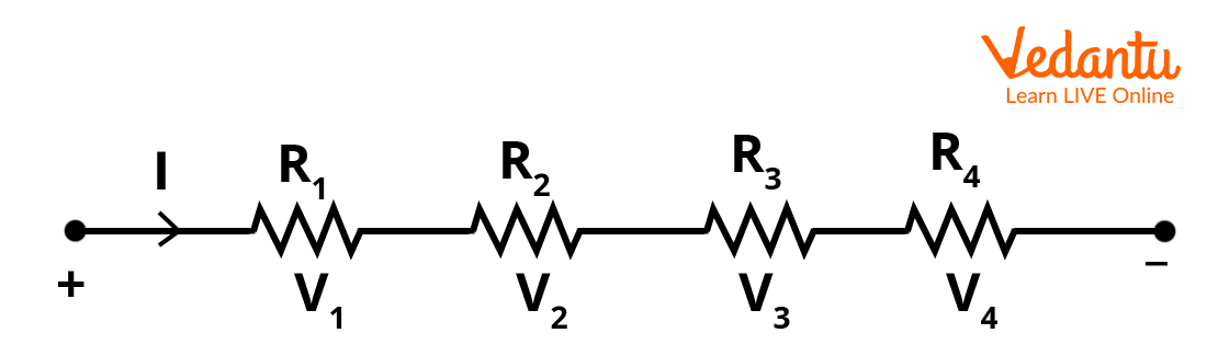
When resistors are connected end-to-end in a single path for current flow, they are said to be in series. In this arrangement, the same current passes sequentially through each resistor, and the potential difference across the network equals the sum of the potential differences across individual resistors.
The formula for equivalent resistance, $R_{eq}$, in a series connection of $n$ resistors $R_1, R_2, \ldots, R_n$ is given by:
$R_{eq} = R_1 + R_2 + R_3 + \ldots + R_n$
The total resistance in series always increases with the addition of more resistors. The equivalent resistance is always greater than the largest individual resistance in the group.
Equivalent Resistance in Parallel Connection
Resistors are considered to be in parallel if both their ends are connected to the same two nodes, providing multiple paths for current. In this configuration, the potential difference across each resistor is equal, while the current divides inversely proportional to each resistance.
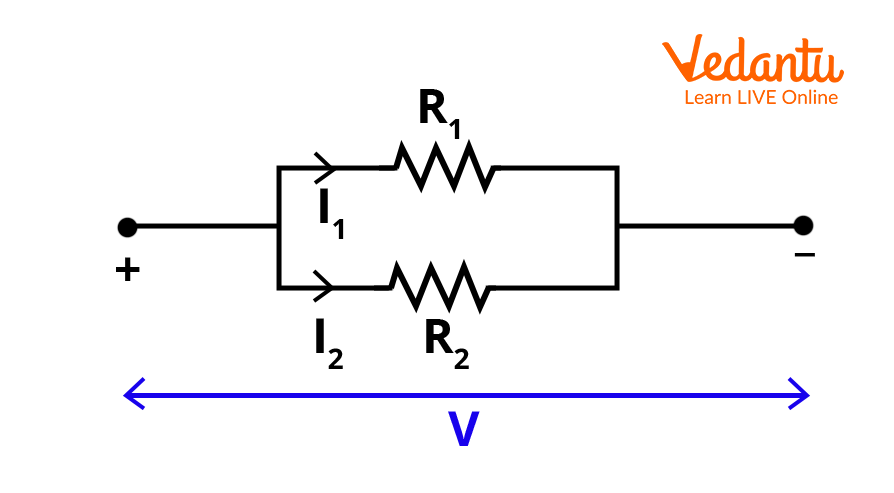
The equivalent resistance, $R_{eq}$, for $n$ resistors $R_1, R_2, \ldots, R_n$ in parallel is calculated as:
$\dfrac{1}{R_{eq}} = \dfrac{1}{R_1} + \dfrac{1}{R_2} + \dfrac{1}{R_3} + \ldots + \dfrac{1}{R_n}$
The equivalent resistance for parallel resistors is always less than the value of the smallest individual resistor. This property allows circuits to achieve lower overall resistance and greater current capacity.
Special Cases: Two Equal Resistors and Standard Combinations
For two resistors $R_1$ and $R_2$ in parallel, the equivalent resistance simplifies to $R_{eq} = \dfrac{R_1 R_2}{R_1 + R_2}$. If all resistors in parallel have the same value $R$, then $R_{eq} = \dfrac{R}{n}$ where $n$ is the number of resistors.
These simplifications are useful for quick calculations and initial estimations during circuit analysis. For additional methods, refer to Circuit Solving Techniques.
Combinations of Series and Parallel Resistances
Complex circuits often contain resistors in both series and parallel arrangements. In such cases, identify simpler series or parallel groups first, replace them with their equivalent resistance, and repeat the process until the full network is reduced to a single equivalent resistance between the specified points.
Step-wise reduction and systematic combination are effective for accurate solutions in extensive resistor networks, especially in examination settings.
Example: Mixed Series and Parallel Network
Consider a circuit with $R_1 = 2~\Omega$ and $R_2 = 4~\Omega$ connected in parallel and this combination connected in series with $R_3 = 3~\Omega$.
First, calculate the parallel equivalent:
$\dfrac{1}{R_p} = \dfrac{1}{2} + \dfrac{1}{4} = \dfrac{3}{4} \implies R_p = \dfrac{4}{3}~\Omega$
Then add $R_3$ in series:
$R_{eq} = R_p + R_3 = \dfrac{4}{3} + 3 = \dfrac{13}{3}~\Omega$
This result demonstrates the correct approach for mixed connection circuits in practice.
Equivalent Resistance in Geometric Configurations
Special circuit geometries, such as resistors arranged in a triangle or a cube, require systematic analysis. In such configurations, resistors may be neither in simple series nor parallel, making direct calculation more involved.
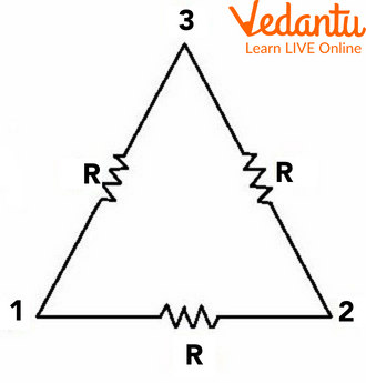
For three resistors of resistance $R$ each arranged in a triangle, the equivalent resistance between two nodes is calculated by considering the series and parallel combinations along different paths between the nodes.
For complex shapes such as cubes or ladder networks, advanced techniques like symmetry analysis, nodal analysis, or the use of Thevenin’s theorem are recommended. For analogous problems in capacitance, see Equivalent Capacitance Explained.
Physical Factors Affecting Resistance
The resistance of a conductor depends on its length $(L)$, cross-sectional area $(A)$, material’s resistivity $(\rho)$, and temperature. The relationship is given by $R = \rho \dfrac{L}{A}$.
A longer conductor or higher resistivity increases resistance, while a larger cross-sectional area decreases it. These principles are vital when selecting materials for circuit design. For further study, refer to Properties of Solids and Liquids.
Important Points about Equivalent Resistance
- In series, $R_{eq}$ increases as more resistors are added
- In parallel, $R_{eq}$ decreases below the smallest resistance
- Series: same current, voltage divides
- Parallel: same voltage, current divides
- Quick formulas exist for identical resistors
- Apply stepwise reduction in complex networks
Summary Table: Series vs. Parallel Equivalent Resistance
| Configuration | Equivalent Resistance Formula |
|---|---|
| Series | $R_{eq} = R_1 + R_2 + \ldots + R_n$ |
| Parallel | $\dfrac{1}{R_{eq}} = \dfrac{1}{R_1} + \dfrac{1}{R_2} + \ldots + \dfrac{1}{R_n}$ |
Applications and Further Study
Understanding equivalent resistance is central to circuit analysis, battery management, and the design of electrical instruments. The concept extends to impedance calculations involving capacitors and inductors. For more advanced circuit scenarios, explore Combination of Capacitors and Basics of Current Electricity.
A solid command over equivalent resistance enables efficient use of Ohm's law and other electrical principles in both theoretical and practical physics problems. To relate this topic with electric potential differences, study Understanding Electric Potential.


FAQs on Understanding Equivalent Resistance in Circuits
1. What is equivalent resistance?
Equivalent resistance is the single resistance that can replace a combination of resistors in a circuit, producing the same total current and voltage as the original arrangement.
- It summarizes the effect of multiple resistors into one value.
- Used to simplify series and parallel circuits.
- Essential for solving CBSE Physics, Class 10 and Class 12 electricity questions.
- Helps in calculating total current and voltage drop in a circuit.
2. How do you find the equivalent resistance in a series circuit?
The equivalent resistance in a series circuit is found by adding the resistance values of each resistor together.
Formula:
- Req = R1 + R2 + R3 + ...
Key Points:
- The current is the same through all resistors.
- The voltage drop is divided across each resistor.
- Used in CBSE and NCERT exams for calculating total resistance in series connection.
3. How do you calculate equivalent resistance in a parallel circuit?
In a parallel circuit, the reciprocal of the equivalent resistance equals the sum of the reciprocals of individual resistances.
Formula:
- 1/Req = 1/R1 + 1/R2 + 1/R3 + ...
Remember:
- Voltage is the same across all branches.
- Current divides among each resistor.
- Used commonly in CBSE Class 10 Science and competitive exams.
4. What happens to the total resistance when more resistors are added in series?
When resistors are added in series, the total (equivalent) resistance increases.
- Each new resistor adds to the overall opposition to current flow.
- Req = R1 + R2 + ...
- Used for managing and controlling current in circuits.
- Important for CBSE exam circuit questions.
5. How does adding more resistors in parallel affect the equivalent resistance?
Adding more resistors in parallel decreases the equivalent resistance of the circuit.
- New pathways for current reduce total opposition.
- Req becomes smaller than the smallest individual resistance.
- Useful in household wiring and electrical safety.
- Key for answering CBSE's electric circuits questions.
6. Why is equivalent resistance important in electrical circuits?
Equivalent resistance allows us to simplify complex circuits and predict how they will behave.
- Makes analysis, calculation, and designing of circuits easier.
- Helps in finding current and voltage in different parts.
- Critical for CBSE syllabus, Physics Class 10 and 12 board exam preparation.
7. What is the formula for combining resistances in series and parallel?
The formulas for equivalent resistance are:
- Series: Req = R1 + R2 + R3 + ...
- Parallel: 1/Req = 1/R1 + 1/R2 + 1/R3 + ...
Use these formulas for both diagram-based and Problem-solving questions in CBSE exams.
8. Can you provide a stepwise method to solve equivalent resistance problems?
To solve equivalent resistance questions:
- Identify if resistors are in series, parallel, or mixed arrangement.
- Apply the series formula where resistors are end-to-end.
- Apply the parallel formula where both ends are connected together.
- Reduce complex networks step by step.
- Re-calculate as you simplify each stage.
Mastering these steps is crucial for CBSE board and competitive exams.
9. What is the SI unit of equivalent resistance?
The SI unit of equivalent resistance is the ohm (Ω).
- It measures how much a resistor opposes electrical current.
- All answers and calculations in board exams should use Ω as the unit.
- Frequently asked in CBSE short answer questions.
10. What are the practical applications of equivalent resistance?
Equivalent resistance is used in circuit analysis, electrical safety, and appliance manufacturing. Some key applications include:
- Simplifying measurement of total resistance in complex circuits
- Designing household wiring
- Calculating current flow to avoid overloading
- Analyzing electronic gadgets and their power ratings
- Frequently tested in both theory and numericals for CBSE board exams
11. What is meant by series and parallel combination of resistors?
Series combination means connecting resistors end-to-end, so current flows through each one in the same path.
Parallel combination means all resistors share both connecting points, splitting the current across multiple paths.
- Series: Same current, voltage divides
- Parallel: Same voltage, current divides
12. In what type of combination does the current remain the same through each resistor?
The current remains the same through each resistor in a series combination.
- Current flows one way through all the resistors.
- Each resistor may have a different voltage drop.
- This point is often tested in CBSE and board exams for conceptual clarity.
13. If three resistors of 2Ω, 3Ω, and 6Ω are connected in parallel, what is the equivalent resistance?
When 2Ω, 3Ω, and 6Ω resistors are connected in parallel:
1/Req = 1/2 + 1/3 + 1/6 = 1
So, Req = 1Ω
- Shows how parallel connections lower overall resistance.
- Important for solving CBSE class 10 and class 12 Physics numericals.