


Make an analysis of the amplitude-modulated wave. Plot the frequency spectrum
Answer
253.2k+ views
Hint: The process of changing the amplitude or frequency or phase of the carrier in accordance with the intensity of the signal is known as modulation. Accordingly, the types of modulations are amplitude modulation (AM), frequency modulation (FM), and phase modulation (PM).
Complete step by step solution:
Let us represent a carrier wave as
${e_c} = {E_c}\cos {\omega _c}t$
where ${e_c}$ stands for the instantaneous voltage, ${E_c}$ stands for the amplitude, and ${\omega _c}$ stands for the angular frequency of the carrier wave.
The modulating signal can be written as,
${e_s} = {E_s}\cos {\omega _s}t$
where ${e_s}$ represent the instantaneous voltage, ${E_s}$ stands for the amplitude, and ${\omega _s}$ stands for the angular frequency of the signal wave.
In an amplitude modulated wave the amplitude of the carrier wave is adjusted in accordance with the intensity of the audio signal.
Therefore the modulated signal can be written as,
$e = \left( {{E_c} + {E_s}\cos {\omega _s}t} \right)\cos {\omega _c}t$
Taking ${E_c}$ outside the bracket, we get
$e = {E_c}\left( {1 + \dfrac{{{E_s}}}{{{E_c}}}\cos {\omega _s}t} \right)\cos {\omega _c}t$
The ratio $\dfrac{{{E_s}}}{{{E_c}}} = m$, where $m$ stands for the modulation factor.
Now the above equation can be written as,
$e = {E_c}\left( {1 + m\cos {\omega _s}t} \right)\cos {\omega _c}t$
Opening the bracket, we get
$e = {E_c}\cos {\omega _c}t + m{E_c}\cos {\omega _c}t.\cos {\omega _s}t$
Multiplying and dividing with $2$in the second half of the above equation, we get
$e = {E_c}\cos {\omega _c}t + \dfrac{{m{E_c}}}{2}\left( {2\cos {\omega _c}t.\cos {\omega _s}t} \right)$
This can be written as,
$e = {E_c}\cos {\omega _c}t + \dfrac{{m{E_c}}}{2}\left[ {\cos \left( {{\omega _c} + {\omega _s}} \right)t + \cos \left( {{\omega _c} - {\omega _s}} \right)t} \right]$
Opening the square bracket, we get
$e = {E_c}\cos {\omega _c}t + \dfrac{{m{E_c}}}{2}\cos \left( {{\omega _c} + {\omega _s}} \right)t + \dfrac{{m{E_c}}}{2}\cos \left( {{\omega _c} - {\omega _s}} \right)t$
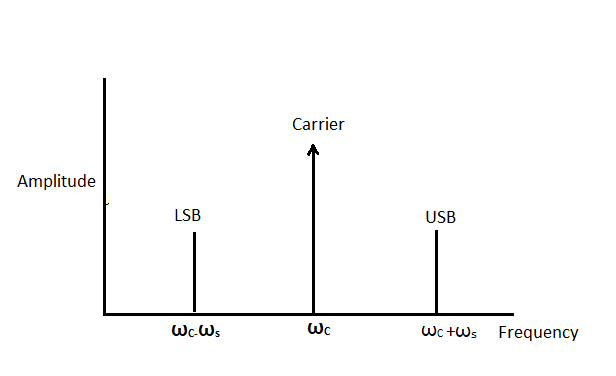
From this expression, we can understand that there are three components in the modulated wave. They are:
${E_c}\cos {\omega _c}t$ : this component is the same as the carrier wave.
$\dfrac{{m{E_c}}}{2}\cos \left( {{\omega _c} + {\omega _s}} \right)t$: The frequency of this component is greater than the carrier and is called the upper side band.
$\dfrac{{m{E_c}}}{2}\cos \left( {{\omega _c} - {\omega _s}} \right)t$: The frequency of this component is lesser than that of the carrier and is called the lower side band.
Frequency spectrum:
Both the lower side band and the upper side band are located on either side of the carrier wave.
Note:
The modulation index or modulation factor is the ratio of change of the amplitude of the carrier wave after modulation to the amplitude of the unmodulated carrier wave. The process of recovering the audio frequency signal from the modulated carrier wave is known as demodulation or detection.
Complete step by step solution:
Let us represent a carrier wave as
${e_c} = {E_c}\cos {\omega _c}t$
where ${e_c}$ stands for the instantaneous voltage, ${E_c}$ stands for the amplitude, and ${\omega _c}$ stands for the angular frequency of the carrier wave.
The modulating signal can be written as,
${e_s} = {E_s}\cos {\omega _s}t$
where ${e_s}$ represent the instantaneous voltage, ${E_s}$ stands for the amplitude, and ${\omega _s}$ stands for the angular frequency of the signal wave.
In an amplitude modulated wave the amplitude of the carrier wave is adjusted in accordance with the intensity of the audio signal.
Therefore the modulated signal can be written as,
$e = \left( {{E_c} + {E_s}\cos {\omega _s}t} \right)\cos {\omega _c}t$
Taking ${E_c}$ outside the bracket, we get
$e = {E_c}\left( {1 + \dfrac{{{E_s}}}{{{E_c}}}\cos {\omega _s}t} \right)\cos {\omega _c}t$
The ratio $\dfrac{{{E_s}}}{{{E_c}}} = m$, where $m$ stands for the modulation factor.
Now the above equation can be written as,
$e = {E_c}\left( {1 + m\cos {\omega _s}t} \right)\cos {\omega _c}t$
Opening the bracket, we get
$e = {E_c}\cos {\omega _c}t + m{E_c}\cos {\omega _c}t.\cos {\omega _s}t$
Multiplying and dividing with $2$in the second half of the above equation, we get
$e = {E_c}\cos {\omega _c}t + \dfrac{{m{E_c}}}{2}\left( {2\cos {\omega _c}t.\cos {\omega _s}t} \right)$
This can be written as,
$e = {E_c}\cos {\omega _c}t + \dfrac{{m{E_c}}}{2}\left[ {\cos \left( {{\omega _c} + {\omega _s}} \right)t + \cos \left( {{\omega _c} - {\omega _s}} \right)t} \right]$
Opening the square bracket, we get
$e = {E_c}\cos {\omega _c}t + \dfrac{{m{E_c}}}{2}\cos \left( {{\omega _c} + {\omega _s}} \right)t + \dfrac{{m{E_c}}}{2}\cos \left( {{\omega _c} - {\omega _s}} \right)t$
From this expression, we can understand that there are three components in the modulated wave. They are:
${E_c}\cos {\omega _c}t$ : this component is the same as the carrier wave.
$\dfrac{{m{E_c}}}{2}\cos \left( {{\omega _c} + {\omega _s}} \right)t$: The frequency of this component is greater than the carrier and is called the upper side band.
$\dfrac{{m{E_c}}}{2}\cos \left( {{\omega _c} - {\omega _s}} \right)t$: The frequency of this component is lesser than that of the carrier and is called the lower side band.
Frequency spectrum:
Both the lower side band and the upper side band are located on either side of the carrier wave.
Note:
The modulation index or modulation factor is the ratio of change of the amplitude of the carrier wave after modulation to the amplitude of the unmodulated carrier wave. The process of recovering the audio frequency signal from the modulated carrier wave is known as demodulation or detection.
Recently Updated Pages
States of Matter Chapter For JEE Main Chemistry
Young’s Double Slit Experiment Derivation Explained
JEE Main Participating Colleges 2026 - A Complete List of Top Colleges
Wheatstone Bridge – Principle, Formula, Diagram & Applications
Circuit Switching vs Packet Switching: Key Differences Explained
Mass vs Weight: Key Differences Explained for Students
Trending doubts
JEE Main 2026: Exam Dates, Session 2 Updates, City Slip, Admit Card & Latest News
JEE Main Marking Scheme 2026- Paper-Wise Marks Distribution and Negative Marking Details
JEE Main 2026 Application Login: Direct Link, Registration, Form Fill, and Steps
Hybridisation in Chemistry – Concept, Types & Applications
Understanding the Electric Field of a Uniformly Charged Ring
Derivation of Equation of Trajectory Explained for Students
Other Pages
CBSE Class 12 Physics Question Paper 2026: Download SET-wise PDF with Answer Key & Analysis
JEE Advanced 2026 - Exam Date (Released), Syllabus, Registration, Eligibility, Preparation, and More
JEE Advanced Marks vs Ranks 2025: Understanding Category-wise Qualifying Marks and Previous Year Cut-offs
JEE Advanced Weightage 2025 Chapter-Wise for Physics, Maths and Chemistry
Ideal and Non-Ideal Solutions Explained for Class 12 Chemistry
JEE Advanced Marks vs Rank 2025 - Predict Your IIT Rank Based on Score