


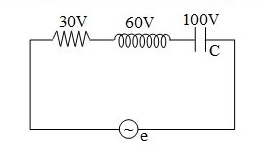
In the given figure, the potential difference is shown on \[R\], \[L\] and \[C\]. The emf of source in volt is
A) \[190\]
B) \[70\]
C) \[50\]
D)\[40\]
Answer
233.1k+ views
Hint: In this question, the given circuit is RLC and AC source is applied, so the concept of the resultant voltage concept will be used that is induction voltage and the capacitance voltage are at same phase while the resistance voltage are at perpendicular phase.
Complete step by step answer:
A standard RLC circuit consists of a resistor, an inductor and a capacitor in series. We consider the voltage across the resistor \[{V_R}\], the voltage across the inductor \[{V_L}\], and the voltage across the capacitor to be \[{V_c}\].
Now this type of circuit has a specific frequency at which it resonates. That is called the resonating frequency.
So, the standard formula to be used in simple series RLC circuit is-
\[ \Rightarrow {V_e} = \sqrt {V_R^2 + {{\left( {{V_L} - {V_C}} \right)}^2}} \]
From the given circuit, we have ${V_R}$ is $30\;{\text{V}}$, ${V_L}$ is $60\;{\text{V}}$, and ${V_C}$ is $100\;{\text{V}}$. Now, we substitute the given values in the above equation as,
\[ \Rightarrow {V_e} = \sqrt {{{30}^2} + {{\left( {60 - 100} \right)}^2}} \]
Now, we simplify the above equation as,
\[ \Rightarrow {V_e} = \sqrt {{{30}^2} + {{\left( { - 40} \right)}^2}} \]
After calculation we get the result as,
\[\therefore V = 50V\]
Hence, the voltage from the emf source obtained across the series combination of the given RLC circuit is \[50V\].
Thus, the correct option is C.
Note: We have seen that the three basic components in a circuit are Resistance, Inductance, and Capacitance have very different phase relationships to each other when connected to a sinusoidal alternating supply which in this case is the source of the emf given. The negative sign in the formula of the net voltage indicates that the inductor is ahead of the capacitance by some degrees phase angle. If the circuit is completely a resistor circuit then the difference in voltages of the other two would have been zero. The resistance of an inductor is \[L\omega \], and that of capacitor is \[\dfrac{1}{{C\omega }}\], where \[C\] is the capacitance and \[L\] is the inductance provided.
Recently Updated Pages
JEE Main 2023 April 6 Shift 1 Question Paper with Answer Key
JEE Main 2023 April 6 Shift 2 Question Paper with Answer Key
JEE Main 2023 (January 31 Evening Shift) Question Paper with Solutions [PDF]
JEE Main 2023 January 30 Shift 2 Question Paper with Answer Key
JEE Main 2023 January 25 Shift 1 Question Paper with Answer Key
JEE Main 2023 January 24 Shift 2 Question Paper with Answer Key
Trending doubts
JEE Main 2026: Session 2 Registration Open, City Intimation Slip, Exam Dates, Syllabus & Eligibility
JEE Main 2026 Application Login: Direct Link, Registration, Form Fill, and Steps
Understanding the Angle of Deviation in a Prism
Hybridisation in Chemistry – Concept, Types & Applications
How to Convert a Galvanometer into an Ammeter or Voltmeter
Understanding Uniform Acceleration in Physics
Other Pages
JEE Advanced Marks vs Ranks 2025: Understanding Category-wise Qualifying Marks and Previous Year Cut-offs
Dual Nature of Radiation and Matter Class 12 Physics Chapter 11 CBSE Notes - 2025-26
Understanding the Electric Field of a Uniformly Charged Ring
JEE Advanced Weightage 2025 Chapter-Wise for Physics, Maths and Chemistry
Derivation of Equation of Trajectory Explained for Students
Understanding Electromagnetic Waves and Their Importance