


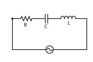
In the given circuit the phase difference between voltage across R and voltage across C is
(A) zero
(B) $\dfrac{\pi }{2}$
(C) $\pi $
(D) $\dfrac{{3\pi }}{2}$
Answer
274.8k+ views
Hint: In an RC ac circuit it is better to draw the phase diagram. It gives a better understanding of phase angles.
Complete step by step solution:
The phase diagram for an ac circuit tells us about the phase angle of current and voltage. It is usually drawn for an RC circuit, RL circuit, LC circuit and RLC circuit. In it we usually find the phase angles of currents flowing through all the elements of the circuit with respect to current through the resistor.
The circuit given in the question is an RLC circuit.
This circuit will have some reactance along with resistance. Also it will not have an equivalent resistance but an equivalent impedance (Z).
This phase difference $\phi $ depends upon the reactive value of the components being used and hopefully we know that reactance, (X) is zero if the circuit element is resistive, positive if the circuit element is inductive and negative if it is capacitive.
Now let’s say that, for current through R, the instantaneous current will be given by;
$i = {i_0}\sin (\omega t)$ (${i_0}$is the maximum value of the current)
Also, instantaneous voltage will be;
${v_r} = {v_0}\sin (\omega t)$ (${v_0}$ is the maximum value of voltage) ---------eq. (1)
But for capacitor the value of instantaneous charge in the capacitor will be;
$q = {q_0}\sin (\omega t) = C{v_0}\sin (\omega t)$ (${q_0}$ is the maximum charge)
Thus by differentiating the above equation with respect to time we get;
${i_c} = C{v_0}\omega \cos (\omega t)$ (${i_c}$ is the instantaneous current through the capacitor)
Hence instantaneous voltage across capacitor is given by;
${i_c}{X_c} = {v_c} = {v_0}\sin (\omega t + \dfrac{\pi }{2})$ -----eq. (2)
From equation: 1 and equation: 2 we get that the angle between the phase of voltage across resistance and phase of voltage across capacitor is 90 degree.
In an ac RLC circuit the instantaneous current through the resistor and voltage across resistor are in phase. But the voltage across the capacitor lags by 90 degrees. The diagram below shows the angle between voltage across resistor and voltage across capacitor is 90 degree.
Hence option (B) is correct.
Note:
1. Voltage across the inductor leads by 90 degrees from voltage across the resistor.
2. Voltage across resistor and current across resistor are in phase.
3. Angle between the phases of voltage across the inductor and voltage across the capacitor is 180 degrees.
Recently Updated Pages
Wheatstone Bridge – Principle, Formula, Diagram & Applications
Mass vs Weight: Key Differences Explained for Students
Circuit Switching vs Packet Switching: Key Differences Explained
Uniform Acceleration Explained: Formula, Examples & Graphs
Young’s Double Slit Experiment Derivation Explained
Classification of Drugs in Chemistry: Types, Examples & Exam Guide
Trending doubts
JEE Main 2026: Exam Dates, Session 2 Updates, City Slip, Admit Card & Latest News
Understanding the Electric Field of a Uniformly Charged Ring
Understanding Atomic Structure for Beginners
Derivation of Equation of Trajectory Explained for Students
Electron Gain Enthalpy and Electron Affinity Explained
How to Convert a Galvanometer into an Ammeter or Voltmeter
Other Pages
CBSE Class 12 Physics Question Paper 2026: Download SET-wise PDF with Answer Key & Analysis
JEE Advanced 2026 Notification Out with Exam Date, Registration (Extended), Syllabus and More
JEE Advanced Percentile vs Marks 2026: JEE Main Cutoff, AIR & IIT Admission Guide
JEE Advanced Weightage Chapter Wise 2026 for Physics, Chemistry, and Mathematics
Understanding Electromagnetic Waves and Their Importance
Class 12 Physics Formulas: Complete Chapter-wise PDF Guide