


In the given A.C. circuit, choose the incorrect statement:
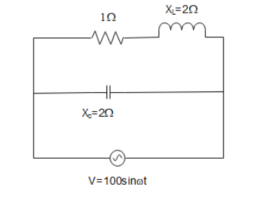
A) Impedance of the circuit is $2\Omega $
B) power factor of the circuit is $1/\sqrt 2 $
C) Peak value of current through resistance is $50\sqrt 2 A$
D) Average power supplied by the source is $2500\,W$
Answer
249.9k+ views
Hint: In this solution, we will use the principles of an LCR circuit under an AC power supply. The impudence of an inductor leads to the resistor’s resistance which in turn leads to the impedance of a capacitor.
Formula used: In this solution, we will use the following formula:
- Impedance of a series LCR circuit: \[z = R + j\left( {{X_L} - {X_C}} \right)\] where $R$ is the resistance, ${X_L}$ is the inductive impedance and ${X_C}$ is the capacitive inductance and $j = \sqrt { - 1} $
- Magnitude of Impedance of a series LCR circuit: \[\left| z \right| = \sqrt {{R^2} + {{\left( {X_L^2 - X_C^2} \right)}^2}} \] where $R$ is the resistance, ${X_L}$ is the inductive impedance, and ${X_C}$ is the capacitive inductance.
Complete step by step answer:
In the given, A.C. circuit, we will check all the options one by one.
To calculate the impedance, we will calculate the impedance of the top branch (containing the resistor and the inductor) and that of the bottom branch (containing the capacitor).
The impedance of the top branch will be
${Z_1} = R + j{X_L}$
$ \Rightarrow {Z_1} = 1 + 1j$
where $j = \sqrt { - 1} $. Similarly, the impedance of the bottom branch will be
${Z_2} = 0 - j{X_C}$
$ \Rightarrow {Z_2} = - 2j$
We want to find the impedance of the circuit in option (A). To do so, we first need to find the phase angle of the top branch with the potential provided by the battery. The angle formed by the top branch will be
$\phi = {\tan ^{ - 1}}\left( {\dfrac{{{X_L}}}{R}} \right)$
Which gives us
$\phi = {\tan ^{ - 1}}\left( {\dfrac{1}{1}} \right)$
$ \Rightarrow \phi = 45^\circ $
And its magnitude will be $\left| {{Z_1}} \right| = \sqrt {{R^2} + X_L^2} $
$ \Rightarrow \left| {{Z_1}} \right| = \sqrt {{1^2} + {1^2}} $
Which gives us
$\left| {{Z_1}} \right| = \sqrt 2 $
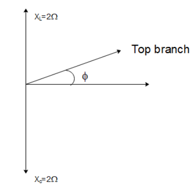
So, the top branch will be leading in phase by $45^\circ $ with the battery potential. The bottom branch only has a capacitor so it will be lagging in phase from the potential by $90^\circ $. So, the net angle between the top branch and the bottom branch will be $90 + 45 = 135^\circ $. So, the net impedance can then be calculated as
\[Z = \sqrt {Z_1^2 + Z_2^2 + 2{Z_1}{Z_2}\cos 135^\circ } \]
\[Z = \sqrt {{{\sqrt 2 }^2} + {2^2} + 2\sqrt 2 (2)\left( {\dfrac{{ - 1}}{{\sqrt 2 }}} \right)} \]
The net magnitude of the impedance of the circuit will be
\[Z = \sqrt {2 + 4 - 4} \]
\[ \Rightarrow Z = \sqrt 2 \]
Hence option (A) is incorrect.
Note: The power factor is the cosine of the angle formed by the current in the circuit with the net impedance. So,
$\cos \theta = \dfrac{R}{Z} = \dfrac{1}{{\sqrt 2 }}$ which is the power factor.
To calculate the average power supplied and the peak current, we have to use the principles of RMS current.
So, ${i_{RMS}} = {V_{RMS}}/{Z_1}$
$ \Rightarrow {i_{RMS}} = \dfrac{{100/\sqrt 2 }}{{\sqrt 2 }} = 50\,A$
Hence the peak current will be
${i_{peak}} = \sqrt 2 {i_{RMS}} = 50\sqrt 2 A$
Formula used: In this solution, we will use the following formula:
- Impedance of a series LCR circuit: \[z = R + j\left( {{X_L} - {X_C}} \right)\] where $R$ is the resistance, ${X_L}$ is the inductive impedance and ${X_C}$ is the capacitive inductance and $j = \sqrt { - 1} $
- Magnitude of Impedance of a series LCR circuit: \[\left| z \right| = \sqrt {{R^2} + {{\left( {X_L^2 - X_C^2} \right)}^2}} \] where $R$ is the resistance, ${X_L}$ is the inductive impedance, and ${X_C}$ is the capacitive inductance.
Complete step by step answer:
In the given, A.C. circuit, we will check all the options one by one.
To calculate the impedance, we will calculate the impedance of the top branch (containing the resistor and the inductor) and that of the bottom branch (containing the capacitor).
The impedance of the top branch will be
${Z_1} = R + j{X_L}$
$ \Rightarrow {Z_1} = 1 + 1j$
where $j = \sqrt { - 1} $. Similarly, the impedance of the bottom branch will be
${Z_2} = 0 - j{X_C}$
$ \Rightarrow {Z_2} = - 2j$
We want to find the impedance of the circuit in option (A). To do so, we first need to find the phase angle of the top branch with the potential provided by the battery. The angle formed by the top branch will be
$\phi = {\tan ^{ - 1}}\left( {\dfrac{{{X_L}}}{R}} \right)$
Which gives us
$\phi = {\tan ^{ - 1}}\left( {\dfrac{1}{1}} \right)$
$ \Rightarrow \phi = 45^\circ $
And its magnitude will be $\left| {{Z_1}} \right| = \sqrt {{R^2} + X_L^2} $
$ \Rightarrow \left| {{Z_1}} \right| = \sqrt {{1^2} + {1^2}} $
Which gives us
$\left| {{Z_1}} \right| = \sqrt 2 $
So, the top branch will be leading in phase by $45^\circ $ with the battery potential. The bottom branch only has a capacitor so it will be lagging in phase from the potential by $90^\circ $. So, the net angle between the top branch and the bottom branch will be $90 + 45 = 135^\circ $. So, the net impedance can then be calculated as
\[Z = \sqrt {Z_1^2 + Z_2^2 + 2{Z_1}{Z_2}\cos 135^\circ } \]
\[Z = \sqrt {{{\sqrt 2 }^2} + {2^2} + 2\sqrt 2 (2)\left( {\dfrac{{ - 1}}{{\sqrt 2 }}} \right)} \]
The net magnitude of the impedance of the circuit will be
\[Z = \sqrt {2 + 4 - 4} \]
\[ \Rightarrow Z = \sqrt 2 \]
Hence option (A) is incorrect.
Note: The power factor is the cosine of the angle formed by the current in the circuit with the net impedance. So,
$\cos \theta = \dfrac{R}{Z} = \dfrac{1}{{\sqrt 2 }}$ which is the power factor.
To calculate the average power supplied and the peak current, we have to use the principles of RMS current.
So, ${i_{RMS}} = {V_{RMS}}/{Z_1}$
$ \Rightarrow {i_{RMS}} = \dfrac{{100/\sqrt 2 }}{{\sqrt 2 }} = 50\,A$
Hence the peak current will be
${i_{peak}} = \sqrt 2 {i_{RMS}} = 50\sqrt 2 A$
Recently Updated Pages
JEE Isolation, Preparation and Properties of Non-metals Important Concepts and Tips for Exam Preparation
Isoelectronic Definition in Chemistry: Meaning, Examples & Trends
Ionisation Energy and Ionisation Potential Explained
Iodoform Reactions - Important Concepts and Tips for JEE
Introduction to Dimensions: Understanding the Basics
Instantaneous Velocity Explained: Formula, Examples & Graphs
Trending doubts
JEE Main 2026: Exam Dates, Session 2 Updates, City Slip, Admit Card & Latest News
Hybridisation in Chemistry – Concept, Types & Applications
JEE Main 2026 Application Login: Direct Link, Registration, Form Fill, and Steps
Understanding the Electric Field of a Uniformly Charged Ring
Derivation of Equation of Trajectory Explained for Students
JEE Main Marking Scheme 2026- Paper-Wise Marks Distribution and Negative Marking Details
Other Pages
CBSE Class 12 Physics Question Paper 2026: Download SET-wise PDF with Answer Key & Analysis
JEE Advanced Marks vs Ranks 2025: Understanding Category-wise Qualifying Marks and Previous Year Cut-offs
JEE Advanced 2026 - Exam Date (Released), Syllabus, Registration, Eligibility, Preparation, and More
JEE Advanced Weightage 2025 Chapter-Wise for Physics, Maths and Chemistry
Understanding the Angle of Deviation in a Prism
Understanding Centrifugal Force in Physics