


In the circuit shown in the figure, the switch is closed at $t = 0$.
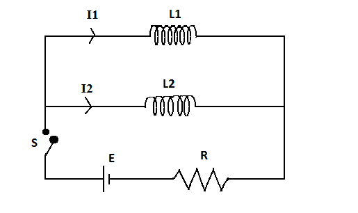
A) At \[t = 0\], ${I_1} = {I_2} = 0$.
B) At any time $t$, $\dfrac{{{I_1}}}{{{I_2}}} = \dfrac{{{L_2}}}{{{L_1}}}$.
C) At any time $t$, ${I_1} + {I_2} = \dfrac{\varepsilon }{R}$.
D) At $t = \infty $, ${I_1}$ and ${I_2}$ are independent of ${L_1}$ and ${L_2}$.
Answer
240.6k+ views
Hint: Using the formula for inductor current of a LR circuit and the given boundary conditions, we will form relations between inductance, current and time. These will give us the correct choices.
Formulae used: Inductor current of a LR circuit: ${I_{ind}} = {I_o}((1 - e)\dfrac{{ - tL}}{R})$.
Where ${I_{ind}}$ is the inductor current and is expressed in Ampere $(A)$, ${I_o}$ is the circuital current and is expressed in Ampere $(A)$, $L$ inductance and is expressed in Henry $(H)$, $R$ is the resistance value and is expressed in Ohms $(\Omega )$ and $t$ is the time taken for the current to change and is expressed in seconds $(s)$.
Induction of an electromagnetic force: $E = L\dfrac{{di}}{{dt}}$
Where $L$ inductance and is expressed in Henry $(H)$, $di$ is the change in current and is expressed in Ampere $(A)$, $dt$ is the time taken for the current to change and is expressed in seconds $(s)$ and $E$ is the emf induced and is expressed in Volt $(V)$. This formula will be used for inductors $1$ and $2$.
Complete step by step solution:
When the switch $S$ is closed, current flows in the circuit due to the battery connected to it. The presence of the inductance coil creates a magnetic flux, which on changing, results in the induction of an electromagnetic force. This is represented by $E$ and is equal to $L\dfrac{{di}}{{dt}}$.
The potential difference across the two parallel connected inductors will be the same at any time $t$,
Therefore we can write,
${L_1}\dfrac{{d{i_1}}}{{dt}} = {L_2}\dfrac{{d{i_2}}}{{dt}}$
Where ${L_1},{L_2}$ are the inductances given and is expressed in Henry $(H)$, $d{i_1},d{i_2}$ are the change in current and is expressed in Ampere $(A)$, $dt$ is the time taken for the current to change and is expressed in seconds $(s)$.
On cancelling out the common factors we establish the relation
\[
\dfrac{{{L_1}}}{{{L_2}}} = \dfrac{{d{i_2}}}{{d{i_1}}} = \dfrac{{{I_{{2_t}}} - {I_2}_o}}{{{I_{{1_t}}} - {I_1}_o}} \\
\Rightarrow \dfrac{{{L_1}}}{{{L_2}}} = \dfrac{{{I_{{2_t}}}}}{{{I_{{1_t}}}}} \\
\]
Rearranging this and rewriting in general terms we get,
$\dfrac{{{I_1}}}{{{I_2}}} = \dfrac{{{L_2}}}{{{L_1}}}$
Now, applying the boundary condition at $t = 0$ we get inductor current,
$
{I_{ind}} = {I_o}((1 - e)\dfrac{{ - tL}}{R}) = {I_o}((1 - e)\dfrac{{ - 0L}}{R}) \\
\Rightarrow {I_{ind}} = 0 \\
$
Therefore at $t = 0$, ${I_{ind}} = 0$.
Now, dividing the inductor current equation by $t$ and applying the boundary conditions at ${t_o} \to \infty $ we get,
$
\Rightarrow {I_{ind}} = {I_o}((1 - e)\dfrac{{ - tL/t}}{{R/t}}) = {I_o}((1 - e)\dfrac{{ - L}}{{R/t}}) \\
\Rightarrow {I_{ind}} = {I_o}((1 - e)\dfrac{{ - L}}{{R/\infty }}) \\
$
As any value by infinity is infinitesimally small, $((1 - e)\dfrac{{ - L}}{{R/\infty }})$ is neglected and we get the value of ${I_{ind}}$ to be as follows,
${I_{ind}} = {I_o}$
This shows that at ${t_o} \to \infty $, the current passing through the inductor is maximum and equal to the circuital current. This proves that at that moment, the inductor current is independent of the values of inductances ${L_1},{L_2}$.
In conclusion, the correct options are (A), (B) and (C).
Additional information: A LR circuit is a circuit having a combination of inductor(s) and resistor(s). In AC circuits, they reduce voltage and in DC circuits, the inductor acts as a static resistance. Therefore, the circuit given in the above problem has AC connection because a resistor is present.
Note: The first boundary condition is at $t = 0$. Similarly, the second one is also at a particular instant of time, that is, $t = {t_\infty }$. Calculations are made to be considered at a given point of time.
Recently Updated Pages
JEE Main 2025-26 Mock Tests: Free Practice Papers & Solutions
JEE Main 2025-26 Experimental Skills Mock Test – Free Practice
JEE Main 2025-26 Electronic Devices Mock Test: Free Practice Online
JEE Main 2025-26 Atoms and Nuclei Mock Test – Free Practice Online
JEE Main 2025-26: Magnetic Effects of Current & Magnetism Mock Test
JEE Main Mock Test 2025: Properties of Solids and Liquids
Trending doubts
JEE Main 2026: Session 1 Results Out and Session 2 Registration Open, City Intimation Slip, Exam Dates, Syllabus & Eligibility
Ideal and Non-Ideal Solutions Explained for Class 12 Chemistry
JEE Main Participating Colleges 2026 - A Complete List of Top Colleges
Clemmensen and Wolff Kishner Reductions Explained for JEE & NEET
Degree of Dissociation: Meaning, Formula, Calculation & Uses
Understanding the Angle of Deviation in a Prism
Other Pages
CBSE Class 12 Physics Question Paper 2026: Download SET-wise PDF with Answer Key & Analysis
JEE Advanced Marks vs Ranks 2025: Understanding Category-wise Qualifying Marks and Previous Year Cut-offs
JEE Advanced 2026 - Exam Date (Released), Syllabus, Registration, Eligibility, Preparation, and More
CBSE Class 12 Physics Question Paper Set 3 (55/2/3) 2025: PDF, Answer Key & Solutions
CBSE Class 12 Physics Question Paper Set 3 (55/1/3) 2025 – PDF, Solutions & Analysis
CBSE Class 12 Physics Question Paper Set 1 (55/1/1) 2025 – PDF, Solutions & Marking Scheme