


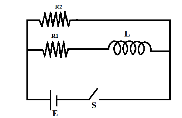
Consider the circuit shown in figure,
A) Find the current through the battery a long time after the switch S is closed.
B) Suppose the switch is opened at t=0, what is the time constant of the decay circuit?
C) Find the current through the inductor after one time constant.
Answer
273k+ views
Hint:When the switch closes the current will flow through the circuit, calculate the current through the circuit after a long time using the formula. Upon closing the switch the resistances become parallel and upon opening the switch the resistances become series. This should be considered while doing the problem.
Formula Used:
i) $i = \dfrac{E}{R}$(Where I stands for the current flowing through the circuit, E stands for the EMF of the cell and R stands for the resistance of the circuit)
ii) $\tau = \dfrac{L}{R}$ (Where $\tau $ stands for the time constant, L stands for the inductance of the circuit, and R stands for the resistance offered by the circuit)
iii) Current through an inductor, $i = {i_0}\left( {1 - {e^{\dfrac{{ - t}}{\tau }}}} \right)$ where (${i_0}$is the steady current through the circuit)
Complete step by step solution:
(A) The battery gets connected to the circuit when the switch is closed and current flows through the L-R circuit. After switching on the circuit for a long time, the current ‘i’ will become constant. Then current flowing through the circuit is given by,
$i = \dfrac{E}{{{R_{total}}}}$…………………………………(1)
Since the resistors are connected in parallel when the switch is on, $\dfrac{1}{{{R_{total}}}} = \dfrac{1}{{{R_1}}} + \dfrac{1}{{{R_2}}}$
$\therefore {R_{total}} = \dfrac{{{R_1}{R_2}}}{{{R_1} + {R_2}}}$
Substituting this value of ${R_{total}}$ in the equation (1), we get
$i = \dfrac{E}{{\dfrac{{{R_1}{R_2}}}{{{R_1} + {R_2}}}}} = \dfrac{{E({R_1} + {R_2})}}{{{R_1}{R_2}}}$
(B) The equation for the time constant is given by, $\tau = \dfrac{L}{R}$
When the switch is opened at $t = 0$, the resistors become series and the total resistance can be written as
${R_{total}} = {R_1} + {R_2}$
Now, we can write the time constant as,
$\tau = \dfrac{L}{{{R_{total}}}} = \dfrac{L}{{{R_1} + {R_2}}}$
(C) Now that the inductor is discharging the current through the two resistor, The current through the inductor after one time constant can be written as,
$i = {i_0}(1 - {e^{\dfrac{{ - t}}{\tau }}})$
When the time constant is one,$t = \tau $
$ \therefore i = {i_0}{e^{\dfrac{{ - \tau }}{\tau }}} $
${i_0}$ can be written as,
$ {i_0} = \dfrac{E}{{{R_1} + {R_2}}} $
$\therefore i = \dfrac{E}{{{R_1} + {R_2}}} \times \dfrac{1}{e} $
Note: An inductor is a coil of wire wound around the central core. An inductor is added to the circuit to make use of its ability to take advantage of the relationship between electricity and magnetism. The current flowing through an inductor circuit will produce a magnetic flux proportional to it. The time needed for an L-R circuit to reach its maximum value is nearly 5 times the value of the time constant ($5\tau $). The current in an inductor will not change instantaneously.
Recently Updated Pages
WBJEE 2026 Result Live: Important Dates, Last Date Apply Online 2026
JoSAA Counselling 2026: JoSAA 2026 Mock Seat Allotment LIVE: Round 2 Result Released, Registration, Choice Filling and Ranks
Circuit Switching vs Packet Switching: Key Differences Explained
JEE General Topics in Chemistry Important Concepts and Tips
JEE Extractive Metallurgy Important Concepts and Tips for Exam Preparation
JEE Atomic Structure and Chemical Bonding important Concepts and Tips
Trending doubts
JEE Main 2026: Exam Dates, Session 2 Updates, City Slip, Admit Card & Latest News
JEE Main Participating Colleges 2026 - A Complete List of Top Colleges
Kinematics Mock Test for JEE Main 2025-26: Comprehensive Practice
Understanding the Electric Field of a Uniformly Charged Ring
Understanding Atomic Structure for Beginners
Derivation of Equation of Trajectory Explained for Students
Other Pages
CBSE Class 12 Physics Question Paper 2026: Download SET-wise PDF with Answer Key & Analysis
JEE Advanced 2026 Notification Out with Exam Date, Registration (Extended), Syllabus and More
JEE Advanced Percentile vs Marks 2026: JEE Main Cutoff, AIR & IIT Admission Guide
JEE Advanced Weightage Chapter Wise 2026 for Physics, Chemistry, and Mathematics
How to Convert a Galvanometer into an Ammeter or Voltmeter
Electron Gain Enthalpy and Electron Affinity Explained