


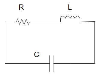
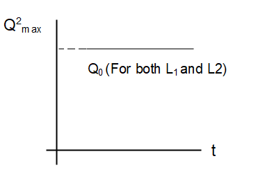
An LCR circuit is equivalent to a damped pendulum. In an LCR circuit, the capacitor is charged to ${Q_0}$ and then connected to the L and R as shown above. If a student plots graphs of the square of maximum charge \[Q_{\max }^2\]on the capacitor with time (t) for two different values \[{L_1}\,\;{\text{and}}\;{L_2}\]\[\left( {{L_1}\, > {L_2}} \right)\] of $L$ then which of the following represents this graph correctly? (plots schematic and not drawn to scale)
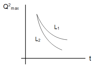
(A)
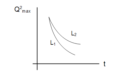
(B)
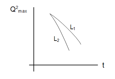
(C)
(D)
Answer
253.5k+ views
Hint: In this solution, we will use the properties of the damped pendulum to determine the charge on the capacitor. The LCR circuit will be equivalent to a spring-mass-dashpot system without any external driving force acting on it.
Formula used: In this question, we will use the following formula
$Q = {Q_0}{e^{ - Rt/2L}}$ where $Q$ is the maximum change in an LCR circuit where ${Q_0}$ is the maximum charge in a capacitor, $R$ is the resistance, and $L$ is the inductance.
Complete step by step answer:
We know that anLCR circuit is equivalent to a damped pendulum and in the question we’ve been told that the capacitor is charged to ${Q_0}$ and then connected to the $L$ and $R$. This system is equivalent to a spring-mass dashpot system. In this system, we have a block that is oscillating connected to a spring and a dashpot. The purpose of the dashpot is to exert friction force on the mass in the system. The drag force exerted by the dashpot will be proportional to the velocity of the mass.
In the spring-mass dashpot case, the amplitude of the block $x$ is defined as a function of time as
$x = {x_0}{e^{ - t/\tau }}$. Here ${x_0}$ is the amplitude of the block, $t$ is the time , $\tau $is the characteristic damping time which depends on the dashpot.
Similarly, the charge on the capacitor as a function of time is given as
$Q = {Q_0}{e^{ - Rt/2L}}$
This is the charge on the capacitor. The behaviour of this graph is such that it exponentially decays with time. The inductor in an LCR circuit acts as the inertia of the circuit. This implies that the higher the inductance of the circuit, the slower the charge decay will be. So as ${L_1} > {L_2}$ has been given to us the charge in ${L_1}$ the circuit will decay slower than the charge in the circuit ${L_2}$
So, option (A) is the correct choice.
Note: To answer this question, we don’t necessarily need to know the properties of the damped oscillation system but since an LCR circuit is very similar, we can use its properties to determine the possible graph of the charge in the circuit.
Recently Updated Pages
States of Matter Chapter For JEE Main Chemistry
Young’s Double Slit Experiment Derivation Explained
JEE Main Participating Colleges 2026 - A Complete List of Top Colleges
Wheatstone Bridge – Principle, Formula, Diagram & Applications
Circuit Switching vs Packet Switching: Key Differences Explained
Mass vs Weight: Key Differences Explained for Students
Trending doubts
JEE Main 2026: Exam Dates, Session 2 Updates, City Slip, Admit Card & Latest News
JEE Main Marking Scheme 2026- Paper-Wise Marks Distribution and Negative Marking Details
JEE Main 2026 Application Login: Direct Link, Registration, Form Fill, and Steps
Hybridisation in Chemistry – Concept, Types & Applications
Understanding the Electric Field of a Uniformly Charged Ring
Derivation of Equation of Trajectory Explained for Students
Other Pages
CBSE Class 12 Physics Question Paper 2026: Download SET-wise PDF with Answer Key & Analysis
JEE Advanced 2026 - Exam Date (Released), Syllabus, Registration, Eligibility, Preparation, and More
JEE Advanced Marks vs Ranks 2025: Understanding Category-wise Qualifying Marks and Previous Year Cut-offs
JEE Advanced Weightage 2025 Chapter-Wise for Physics, Maths and Chemistry
Ideal and Non-Ideal Solutions Explained for Class 12 Chemistry
JEE Advanced Marks vs Rank 2025 - Predict Your IIT Rank Based on Score