


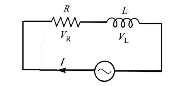
An inductor and resistor are connected in series with an AC source. In this circuit,
The current and the PD across resistance lead the PD across the inductance.
(A) The current and the PD across the resistance lag behind the PD across the inductance by angle $\dfrac{\pi }{2}$
(B) The current and the PD across the resistance lag behind the PD across the inductance by an angle $\pi $
(C) The PD across the resistance lags behind the PD across the inductance by an angle (D)$\dfrac{\pi }{2}$ but the current in resistance leads the PD across the inductance by $\dfrac{\pi }{2}$.
Answer
249.3k+ views
Hint Find the impedance for series resistance and inductor AC circuit then, draw the phasor diagram of series inductance and resistance series AC circuit. In the phasor diagram, draw the voltage across resistance and also draw the voltage across inductance. If the angle of voltage across inductance is greater then it leads the voltage across resistance.
Step by Step Solution
Let the resistance and inductance be R and L respectively
Construct a series L-R AC circuit
Now, we get
${V_{net}} = {\vec V_L} + {\vec V_R}$
By taking magnitude
\[
\left| {{{\vec V}_{net}}} \right| = \sqrt {({V^2}_L + {V^2}_R)} \\
\left| {{{\vec V}_{net}}} \right| = \sqrt {({i^2}{X^2}_L + {i^2}{R^2})} \\
\\
\]
By taking ${i^2}$ common
\[\left| {{{\vec V}_{net}}} \right| = i\sqrt {({X^2}_L + {R^2})} \]
To calculate the impedance let impedance be $Z$
$Z = \dfrac{V}{i} = \sqrt {({X_L}^2 + {R^2})} $
Because, ${X_L} = \omega L$ we get
$Z = \sqrt {({\omega ^2}{L^2} + {R^2})} $
This is the impedance for series L-R AC circuit
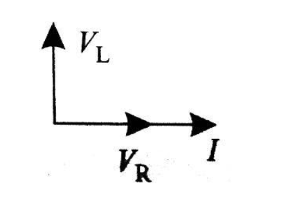
Now, draw the phasor diagram for series L-R AC circuit
$
\tan \varphi = \dfrac{{{V_L}}}{{{V_R}}} \\
\tan \varphi = \dfrac{{i{X_L}}}{{iR}} \\
\\
$
Now, we get
$\varphi = {\tan ^{ - 1}}\left( {\dfrac{{{X_L}}}{R}} \right)$
Therefore, after seeing the phasor diagram we can easily conclude that potential difference across inductance leads the current and potential difference across resistance by an angle $\dfrac{\pi }{2}$
Hence, option (B) is the correct answer.
Note resistance is the measure of the opposition of current in the circuit. It is denoted by R. It is measured in ohms $(\Omega )$.
Inductance is the property of a conductor to oppose the flow of electric current through it. The flow of current makes a magnetic field around the conductor. It is denoted by L. It is measured in Henry $(H)$.
Step by Step Solution
Let the resistance and inductance be R and L respectively
Construct a series L-R AC circuit
Now, we get
${V_{net}} = {\vec V_L} + {\vec V_R}$
By taking magnitude
\[
\left| {{{\vec V}_{net}}} \right| = \sqrt {({V^2}_L + {V^2}_R)} \\
\left| {{{\vec V}_{net}}} \right| = \sqrt {({i^2}{X^2}_L + {i^2}{R^2})} \\
\\
\]
By taking ${i^2}$ common
\[\left| {{{\vec V}_{net}}} \right| = i\sqrt {({X^2}_L + {R^2})} \]
To calculate the impedance let impedance be $Z$
$Z = \dfrac{V}{i} = \sqrt {({X_L}^2 + {R^2})} $
Because, ${X_L} = \omega L$ we get
$Z = \sqrt {({\omega ^2}{L^2} + {R^2})} $
This is the impedance for series L-R AC circuit
Now, draw the phasor diagram for series L-R AC circuit
$
\tan \varphi = \dfrac{{{V_L}}}{{{V_R}}} \\
\tan \varphi = \dfrac{{i{X_L}}}{{iR}} \\
\\
$
Now, we get
$\varphi = {\tan ^{ - 1}}\left( {\dfrac{{{X_L}}}{R}} \right)$
Therefore, after seeing the phasor diagram we can easily conclude that potential difference across inductance leads the current and potential difference across resistance by an angle $\dfrac{\pi }{2}$
Hence, option (B) is the correct answer.
Note resistance is the measure of the opposition of current in the circuit. It is denoted by R. It is measured in ohms $(\Omega )$.
Inductance is the property of a conductor to oppose the flow of electric current through it. The flow of current makes a magnetic field around the conductor. It is denoted by L. It is measured in Henry $(H)$.
Recently Updated Pages
JEE Isolation, Preparation and Properties of Non-metals Important Concepts and Tips for Exam Preparation
Isoelectronic Definition in Chemistry: Meaning, Examples & Trends
Ionisation Energy and Ionisation Potential Explained
Iodoform Reactions - Important Concepts and Tips for JEE
Introduction to Dimensions: Understanding the Basics
Instantaneous Velocity Explained: Formula, Examples & Graphs
Trending doubts
JEE Main 2026: Exam Dates, Session 2 Updates, City Slip, Admit Card & Latest News
Hybridisation in Chemistry – Concept, Types & Applications
JEE Main 2026 Application Login: Direct Link, Registration, Form Fill, and Steps
Understanding the Electric Field of a Uniformly Charged Ring
Derivation of Equation of Trajectory Explained for Students
JEE Main Marking Scheme 2026- Paper-Wise Marks Distribution and Negative Marking Details
Other Pages
CBSE Class 12 Physics Question Paper 2026: Download SET-wise PDF with Answer Key & Analysis
JEE Advanced Marks vs Ranks 2025: Understanding Category-wise Qualifying Marks and Previous Year Cut-offs
JEE Advanced 2026 - Exam Date (Released), Syllabus, Registration, Eligibility, Preparation, and More
JEE Advanced Weightage 2025 Chapter-Wise for Physics, Maths and Chemistry
Understanding the Angle of Deviation in a Prism
Understanding Centrifugal Force in Physics