


An ammeter having resistance ${R_0}$ shows full deflection when the current $I$ flow from it. What resistance should be connected to it in series so that it shows deflection $\dfrac{I}{n}$ when the same current flows.
A) $\dfrac{{{R_0}}}{n}$
B) ${R_0}\left( {n - 1} \right)$
C) $\dfrac{{{R_0}}}{{n + 1}}$
D) None of these
Answer
253.5k+ views
Hint: To solve this question, we have to understand the arrangement in which a galvanometer can be converted to an ammeter. To convert a galvanometer to ammeter, a resistor of very low resistance called shunt resistance should be connected in parallel to the galvanometer.
Complete step by step solution:
An ammeter is a device used to measure the magnitude of current flowing through the wire. It is connected in the series with the branch in which current has to be measured.
An ammeter can be constructed from a galvanometer by connecting a low resistance in parallel to the galvanometer as shown:
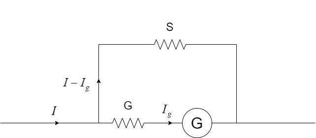
If G is the resistance of the galvanometer, $I$ is the current to be measured and ${I_g}$ is the current flowing through the galvanometer, the value of shunt resistance connected to the galvanometer is given by –
$S = \dfrac{{G{I_g}}}{{I - {I_g}}}$
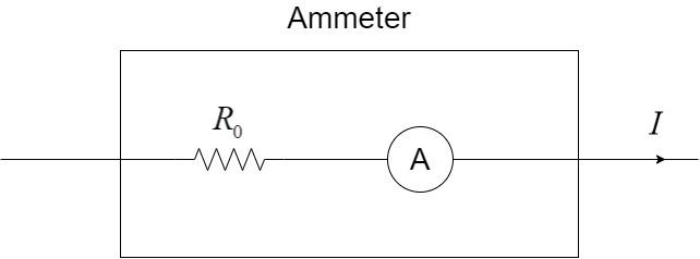
Thus, the complete setup can be summarised as the schematic figure of an ammeter with a resistance which is given here, as ${R_0}$ with the current I flowing through the ammeter.
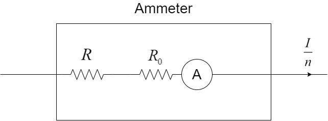
Let R be another resistance connected in series with ${R_0}$ such that the current flowing through the ammeter shall be $\dfrac{I}{n}$ as shown:
In both the cases, the voltage drop across the ammeter remains constant since the current flowing is the same in both the cases.
Voltage drop in the first case: $V = I{R_0}$
Voltage drop in the second case: $V = \dfrac{I}{n}\left( {R + {R_0}} \right)$
Equating them, we get –
$I{R_0} = \dfrac{I}{n}\left( {R + {R_0}} \right)$
$ \Rightarrow {R_0} = \dfrac{{R + {R_0}}}{n}$
$ \Rightarrow n{R_0} = R + {R_0}$
$ \Rightarrow R = n{R_0} - {R_0}$
$ \Rightarrow R = {R_0}\left( {n - 1} \right)$
Hence, the correct option is Option B.
Note: The students must note the fact that in an ammeter, the shunt resistor used, has a very low value, usually in micro- or milli- ohms. If you encounter any problem on calculating the shunt resistance in an ammeter and you do not get a low resistance, it is sure that the solution is headed in the wrong direction.
Complete step by step solution:
An ammeter is a device used to measure the magnitude of current flowing through the wire. It is connected in the series with the branch in which current has to be measured.
An ammeter can be constructed from a galvanometer by connecting a low resistance in parallel to the galvanometer as shown:
If G is the resistance of the galvanometer, $I$ is the current to be measured and ${I_g}$ is the current flowing through the galvanometer, the value of shunt resistance connected to the galvanometer is given by –
$S = \dfrac{{G{I_g}}}{{I - {I_g}}}$
Thus, the complete setup can be summarised as the schematic figure of an ammeter with a resistance which is given here, as ${R_0}$ with the current I flowing through the ammeter.
Let R be another resistance connected in series with ${R_0}$ such that the current flowing through the ammeter shall be $\dfrac{I}{n}$ as shown:
In both the cases, the voltage drop across the ammeter remains constant since the current flowing is the same in both the cases.
Voltage drop in the first case: $V = I{R_0}$
Voltage drop in the second case: $V = \dfrac{I}{n}\left( {R + {R_0}} \right)$
Equating them, we get –
$I{R_0} = \dfrac{I}{n}\left( {R + {R_0}} \right)$
$ \Rightarrow {R_0} = \dfrac{{R + {R_0}}}{n}$
$ \Rightarrow n{R_0} = R + {R_0}$
$ \Rightarrow R = n{R_0} - {R_0}$
$ \Rightarrow R = {R_0}\left( {n - 1} \right)$
Hence, the correct option is Option B.
Note: The students must note the fact that in an ammeter, the shunt resistor used, has a very low value, usually in micro- or milli- ohms. If you encounter any problem on calculating the shunt resistance in an ammeter and you do not get a low resistance, it is sure that the solution is headed in the wrong direction.
Recently Updated Pages
States of Matter Chapter For JEE Main Chemistry
Young’s Double Slit Experiment Derivation Explained
JEE Main Participating Colleges 2026 - A Complete List of Top Colleges
Wheatstone Bridge – Principle, Formula, Diagram & Applications
Circuit Switching vs Packet Switching: Key Differences Explained
Mass vs Weight: Key Differences Explained for Students
Trending doubts
JEE Main 2026: Exam Dates, Session 2 Updates, City Slip, Admit Card & Latest News
JEE Main Marking Scheme 2026- Paper-Wise Marks Distribution and Negative Marking Details
JEE Main 2026 Application Login: Direct Link, Registration, Form Fill, and Steps
Hybridisation in Chemistry – Concept, Types & Applications
Understanding the Electric Field of a Uniformly Charged Ring
Derivation of Equation of Trajectory Explained for Students
Other Pages
CBSE Class 12 Physics Question Paper 2026: Download SET-wise PDF with Answer Key & Analysis
JEE Advanced 2026 - Exam Date (Released), Syllabus, Registration, Eligibility, Preparation, and More
JEE Advanced Marks vs Ranks 2025: Understanding Category-wise Qualifying Marks and Previous Year Cut-offs
JEE Advanced Weightage 2025 Chapter-Wise for Physics, Maths and Chemistry
Ideal and Non-Ideal Solutions Explained for Class 12 Chemistry
JEE Advanced Marks vs Rank 2025 - Predict Your IIT Rank Based on Score