


How is a p-n junction diode used as a half wave rectifier? Explain its working, draw a neat circuit diagram. Show the waveforms of input and output voltages.
Answer
565.7k+ views
Hint: A p-n junction diode can work as an excellent rectifier since it offers a low resistance for the current to flow when it is forward biased; but a very high resistance when reverse biased. Thus, it allows current through it only in one direction and acts as a rectifier.
Complete step by step answer:
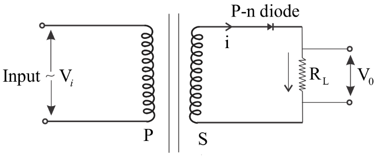
Basically, a rectifier is a device which converts an alternating current into a direct current. A half-wave rectifier consists of a transformer, a diode and a load resistor. The primary coil of the transformer is connected to the ac mains, and the secondary coil to a load resistor $${{\text{R}}_{\text{L}}}$$ through the diode D as shown below in figure: -
The waveforms of input and the corresponding output voltages are as shown below:-
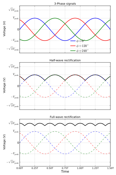
During the positive half-cycle of the input voltage sine wave, the p-n junction diode is forward-biased and hence it conducts through ${{\text{R}}_{\text{L}}}$. The current flowing in the circuit produces a voltage across the load which has the same shape as the positive half-cycle of the input voltage ${{\text{V}}_{\text{i}}}$. During the next half-cycle of the sine wave, the p-n junction diode is reverse-biased. Hence, during this time, no current flows in the circuit and no voltage develops across ${{\text{R}}_{\text{L}}}$. Since only the positive half-cycle of the input appears across the load, the input ac voltage is converted into a pulsating dc voltage. This process is repeated. This process is called Half-Wave Rectification.
Note: The purpose of the transformer is to supply the necessary voltage to the rectifier. It may be a step-up or step-down depending on the requirement. The ratio of RMS value of AC component to DC component in the rectifier is called ripple factor.
Complete step by step answer:
Basically, a rectifier is a device which converts an alternating current into a direct current. A half-wave rectifier consists of a transformer, a diode and a load resistor. The primary coil of the transformer is connected to the ac mains, and the secondary coil to a load resistor $${{\text{R}}_{\text{L}}}$$ through the diode D as shown below in figure: -
The waveforms of input and the corresponding output voltages are as shown below:-
During the positive half-cycle of the input voltage sine wave, the p-n junction diode is forward-biased and hence it conducts through ${{\text{R}}_{\text{L}}}$. The current flowing in the circuit produces a voltage across the load which has the same shape as the positive half-cycle of the input voltage ${{\text{V}}_{\text{i}}}$. During the next half-cycle of the sine wave, the p-n junction diode is reverse-biased. Hence, during this time, no current flows in the circuit and no voltage develops across ${{\text{R}}_{\text{L}}}$. Since only the positive half-cycle of the input appears across the load, the input ac voltage is converted into a pulsating dc voltage. This process is repeated. This process is called Half-Wave Rectification.
Note: The purpose of the transformer is to supply the necessary voltage to the rectifier. It may be a step-up or step-down depending on the requirement. The ratio of RMS value of AC component to DC component in the rectifier is called ripple factor.
Recently Updated Pages
Circuit Switching vs Packet Switching: Key Differences Explained
Dimensions of Pressure in Physics: Formula, Derivation & SI Unit
JEE General Topics in Chemistry Important Concepts and Tips
JEE Extractive Metallurgy Important Concepts and Tips for Exam Preparation
JEE Atomic Structure and Chemical Bonding important Concepts and Tips
JEE Amino Acids and Peptides Important Concepts and Tips for Exam Preparation
Trending doubts
JEE Main Marking Scheme 2026- Paper-Wise Marks Distribution and Negative Marking Details
Electron Gain Enthalpy and Electron Affinity Explained
Understanding Instantaneous Velocity
JEE Main Colleges 2026: Complete List of Participating Institutes
Hybridisation in Chemistry – Concept, Types & Applications
Ideal and Non-Ideal Solutions Explained for Class 12 Chemistry
Other Pages
JEE Advanced 2026 Marks vs Rank: Estimate IIT Rank from Your Score
CBSE Notes Class 11 Physics Chapter 9 - Mechanical Properties of Fluids - 2026-27
CBSE Notes Class 11 Physics Chapter 6 - System of Particles and Rotational Motion - 2026-27
A car is moving with speed 30 ms on a circular path class 11 physics JEE_Main
CBSE Notes Class 11 Physics Chapter 11 - Thermodynamics - 2025-26
Understanding Displacement and Velocity Time Graphs