


A 3 Volt battery with negligible internal resistance is connected in a circuit as shown in the figure. The current I in the circuit will be
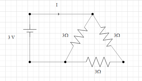
A) $1\,A$
B) $1.5\,A$
C) $2\,A$
D) $\dfrac{1}{3}\,A$
Answer
233.1k+ views
Hint:We can use ohm's law to solve this question. According to ohm's law voltage is directly proportional to current. If we find the total effective resistance in the circuit then we can find the value of current. The total resistance in series will be the sum of individual resistances and the total resistance in parallel can be found by adding the reciprocals of individual resistance and then taking the reciprocal of the total sum obtained.
Complete step by step solution:
It is given that the voltage in the circuit is $V = 3\,V$
The internal resistance of the battery is negligible so it can be taken as zero.
Three resistance are connected in the circuit. We need to find the current flowing through the circuit for the given arrangement of resistors.
We know that from ohm's law voltage is directly proportional to current.
$V \propto I$
That is ,
$V = IR$
Where V is the voltage, I is the current and R is the resistance.
If we know the total resistance of the circuit then we can find the current flowing through the circuit using this formula.
So, let's find the effective resistance of the given arrangement.
Let us name the resistors as ${R_1}$, ${R_2}$ and ${R_3}$ as shown below
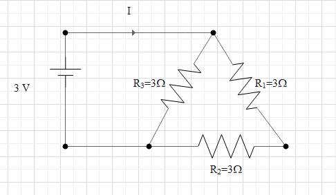
We can see that ${R_1}$ and ${R_2}$ are in series since only one end is connected.
When resistances are connected in series the total resistance is given by the sum of individual resistance.
${R_S} = {R_1} + {R_2}$
Using this the total resistance here is
${R_S} = 3 + 3 = 6\,\Omega $
Now from the figure we can see that this effective series resistance is parallel to ${R_3}$ since both ends of ${R_3}$ are connected to the two ends of effective series resistance.
When resistors are connected in parallel total resistance is given as
$\dfrac{1}{{{R_P}}} = \dfrac{1}{{{R_1}}} + \dfrac{1}{{{R_2}}}$
Here the resistance in parallel are ${R_S}$ and ${R_3}$
Thus, we can write,
$\dfrac{1}{{{R_P}}} = \dfrac{1}{{{R_S}}} + \dfrac{1}{{{R_3}}}$
$ \Rightarrow \dfrac{1}{{{R_P}}} = \dfrac{1}{6} + \dfrac{1}{3}$
$ \Rightarrow \dfrac{1}{{{R_P}}} = \dfrac{3}{6}$
$\therefore {R_P} = 2\Omega $
This is the net resistance in the given circuit.
Let us substitute this value in the equation for ohm's law.
$V = IR$
$ \Rightarrow 3 = I \times 2$
$\therefore I = 1.5\,A$
This is the current flowing in the circuit.
Therefore, the correct answer is option B.
Note: While calculating the effective resistance don’t think that the three resistances are in series since they are arranged end to end. Consider the potential at the ends to check whether the connection is series or parallel. The two ends of ${R_3}$ and the ends of the branch containing ${R_2}$ and ${R_1}$ are connected together. And only one end of ${R_1}$ is connected to ${R_2}$ .Thus ${R_1}$ and ${R_2}$ are in series and their effective resistance is parallel to ${R_3}$ .
Complete step by step solution:
It is given that the voltage in the circuit is $V = 3\,V$
The internal resistance of the battery is negligible so it can be taken as zero.
Three resistance are connected in the circuit. We need to find the current flowing through the circuit for the given arrangement of resistors.
We know that from ohm's law voltage is directly proportional to current.
$V \propto I$
That is ,
$V = IR$
Where V is the voltage, I is the current and R is the resistance.
If we know the total resistance of the circuit then we can find the current flowing through the circuit using this formula.
So, let's find the effective resistance of the given arrangement.
Let us name the resistors as ${R_1}$, ${R_2}$ and ${R_3}$ as shown below
We can see that ${R_1}$ and ${R_2}$ are in series since only one end is connected.
When resistances are connected in series the total resistance is given by the sum of individual resistance.
${R_S} = {R_1} + {R_2}$
Using this the total resistance here is
${R_S} = 3 + 3 = 6\,\Omega $
Now from the figure we can see that this effective series resistance is parallel to ${R_3}$ since both ends of ${R_3}$ are connected to the two ends of effective series resistance.
When resistors are connected in parallel total resistance is given as
$\dfrac{1}{{{R_P}}} = \dfrac{1}{{{R_1}}} + \dfrac{1}{{{R_2}}}$
Here the resistance in parallel are ${R_S}$ and ${R_3}$
Thus, we can write,
$\dfrac{1}{{{R_P}}} = \dfrac{1}{{{R_S}}} + \dfrac{1}{{{R_3}}}$
$ \Rightarrow \dfrac{1}{{{R_P}}} = \dfrac{1}{6} + \dfrac{1}{3}$
$ \Rightarrow \dfrac{1}{{{R_P}}} = \dfrac{3}{6}$
$\therefore {R_P} = 2\Omega $
This is the net resistance in the given circuit.
Let us substitute this value in the equation for ohm's law.
$V = IR$
$ \Rightarrow 3 = I \times 2$
$\therefore I = 1.5\,A$
This is the current flowing in the circuit.
Therefore, the correct answer is option B.
Note: While calculating the effective resistance don’t think that the three resistances are in series since they are arranged end to end. Consider the potential at the ends to check whether the connection is series or parallel. The two ends of ${R_3}$ and the ends of the branch containing ${R_2}$ and ${R_1}$ are connected together. And only one end of ${R_1}$ is connected to ${R_2}$ .Thus ${R_1}$ and ${R_2}$ are in series and their effective resistance is parallel to ${R_3}$ .
Recently Updated Pages
JEE Main 2023 April 6 Shift 1 Question Paper with Answer Key
JEE Main 2023 April 6 Shift 2 Question Paper with Answer Key
JEE Main 2023 (January 31 Evening Shift) Question Paper with Solutions [PDF]
JEE Main 2023 January 30 Shift 2 Question Paper with Answer Key
JEE Main 2023 January 25 Shift 1 Question Paper with Answer Key
JEE Main 2023 January 24 Shift 2 Question Paper with Answer Key
Trending doubts
JEE Main 2026: Session 2 Registration Open, City Intimation Slip, Exam Dates, Syllabus & Eligibility
JEE Main 2026 Application Login: Direct Link, Registration, Form Fill, and Steps
Understanding the Angle of Deviation in a Prism
Hybridisation in Chemistry – Concept, Types & Applications
How to Convert a Galvanometer into an Ammeter or Voltmeter
Understanding Uniform Acceleration in Physics
Other Pages
JEE Advanced Marks vs Ranks 2025: Understanding Category-wise Qualifying Marks and Previous Year Cut-offs
Dual Nature of Radiation and Matter Class 12 Physics Chapter 11 CBSE Notes - 2025-26
Understanding the Electric Field of a Uniformly Charged Ring
JEE Advanced Weightage 2025 Chapter-Wise for Physics, Maths and Chemistry
Derivation of Equation of Trajectory Explained for Students
Understanding Electromagnetic Waves and Their Importance