


Key Features and Applications of Transformer Models
A transformer is one of the most important electrical devices in modern power systems. Its primary function is to alter the voltage of alternating current (AC) for various applications, making energy transfer safer and more efficient. In JEE Physics, understanding transformers is crucial as it forms the backbone of electricity distribution and transmission networks. Vedantu offers detailed insights on this topic to simplify concepts for aspirants preparing for competitive exams.
What is a Transformer and Why is It Important?
A transformer is an electromagnetic device that transfers electrical energy from one circuit to another using mutual induction. This process allows for the change of voltage level without any change in frequency. Transformers play a central role in the transmission of electrical power over long distances, improving efficiency while limiting energy loss. For instance, the presence of a transformer in household circuits ensures safe voltage for everyday appliances.
Key Functions: How Does a Transformer Work?
Transformers function based on electromagnetic induction. When an alternating voltage is applied to the primary coil, it generates a time-varying magnetic field. This flux links with the secondary coil through a shared magnetic core and induces a voltage according to Faraday’s Law. The amount of voltage induced depends on the ratio of turns between the coils. The working principle of transformer guarantees efficient voltage adjustment without direct electrical connection.

- Voltage transformation between different AC circuits
- Safe and loss-minimised long-distance power transfer
- Enables household and industrial use of electricity
- Functions strictly for AC, not suitable for DC circuits
- Relies solely on mutual induction principle
Types of Transformers
There are several types of transformers, each designed for specific voltage or measurement needs. The most widely used are step up and step down transformers, with others fulfilling roles such as measurement and protection. To know further details, you can explore the in-depth explanations at Step-Up Transformer and Step-Down Transformer pages on Vedantu.
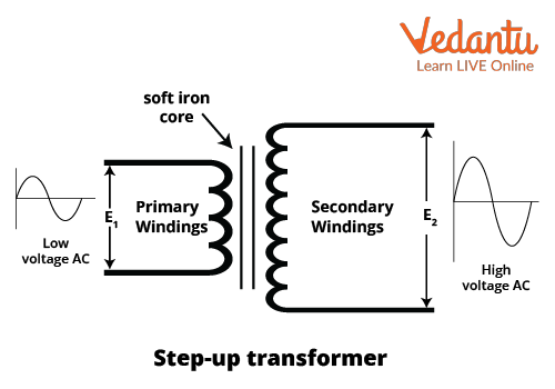
- Step Up Transformer – increases the secondary voltage
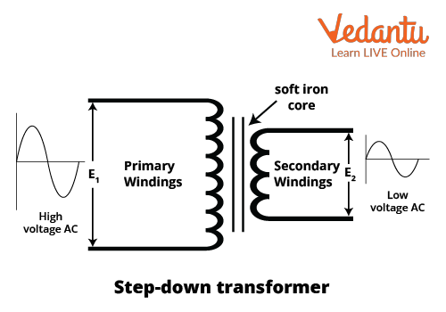
- Step Down Transformer – lowers the secondary voltage
- Iron Core Transformer – for high-efficiency power networks
- Air Core Transformer – used in high-frequency circuits
- Autotransformer – single winding for variable voltage
- Power Transformer – for high-power transmission stations
- Distribution Transformer – supplies power to consumers
- Measurement Transformer – current and voltage measurement
- Protection Transformer – shields sensitive devices
Step-up transformers are often found in power plants, while step-down transformers are used nearer to consumers’ homes and industries. Specialist transformers are vital for measurement and safety, operating as current or potential transformers in instrumentation circuits.
Essential Components of a Transformer
Every transformer comprises key components that determine its function and efficiency. The main elements include:
- Primary winding for incoming AC supply
- Secondary winding to provide output voltage
- Magnetic core (laminated iron) for magnetic flux
- Insulation agents (oil or paper) to prevent breakdown
- Enclosure and cooling system for protection
Construction Details and Working Principle
The construction of a transformer involves two windings (primary and secondary) wound on a common iron core. The core is laminated to minimise eddy current losses and increase efficiency. High-grade insulation materials are used between layers and coils to withstand high voltages and protect against breakdown.
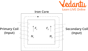
When AC passes through the primary winding, magnetic flux is generated in the core, which induces a voltage in the secondary winding. The voltage ratio between the coils is defined by the turns ratio, as shown below:
| Parameter | Relationship |
|---|---|
| Turns Ratio | $\dfrac{N_1}{N_2}$ |
| Voltage Ratio | $\dfrac{E_1}{E_2} = \dfrac{N_1}{N_2}$ |
| Power Efficiency | $\eta = \dfrac{Output}{Input} \times 100$ |
For a step-up transformer, the number of turns in the secondary coil exceeds that in the primary. For step-down transformers, it’s the reverse. This principle is central to efficient electricity transmission across regions.
Applications of Transformers in Daily Life
Transformers are vital to numerous real-world systems. Their ability to change voltage ensures both safety and efficiency in electricity use and delivery. Apart from power transmission, transformers also feature in measurement, control, and protection circuits across industries and homes.
- High-voltage power transmission over long distances
- Voltage regulation for reliable electricity supply
- Supplying safe low voltages to homes and offices
- Current and voltage measurement accuracy
- Protection against electrical surges and faults
Understanding the applications of transformers helps clarify the distinction between technical devices and cultural references such as transformers movies or other popular media. While both share the same word, their meanings are context-dependent. For engineering and JEE purposes, transformer knowledge is essential for solving circuit and power-related problems.
Transformer Efficiency and Losses
Transformer efficiency refers to the ratio of output power delivered to the load versus the input power supplied. High-efficiency transformers are fundamental to minimising transmission losses, making electrical grids more economical. Losses in transformers mostly arise due to winding resistance, core (iron) losses, and minor stray losses. Modern devices, such as those found in the latest transformers cast installations, are designed to limit these challenges for better performance.
| Type of Loss | Cause |
|---|---|
| Copper Loss | Resistance in windings |
| Iron Loss | Eddy currents & hysteresis |
| Stray Loss | Leakage flux & imperfect connections |
Transformer Table: Voltage and Turns Ratio at a Glance
Data tables help summarise how transformers operate under different conditions. The following transformer table gives a quick reference for standard JEE-type problems regarding voltage and winding turns.
| Transformer Type | Turns Ratio ($N_2:N_1$) | Voltage Ratio ($V_2:V_1$) |
|---|---|---|
| Step Up | > 1 | > 1 |
| Step Down | < 1 | < 1 |
| Isolation | = 1 | = 1 |
For deeper theoretical concepts and calculations, consult Vedantu’s resources on Transformer Overview or related physics topics for JEE. Exploring topics such as transformers movies or transformers in order can be fun, but academic mastery lies in understanding real physics principles and problem-solving techniques.
How Transformers Are Used Across Domains
The use of transformers is not restricted to power supply alone. Industries, research labs, medical equipment, and precise measurement instruments all rely on transformers for stability and safety. Whether in small chargers or ultra-high-voltage substations, the same concept underlies all transformers, from the simplest designs to complex installations referenced as advanced transformers rise of the beasts systems.
- Efficient distribution of electricity in smart grids
- Safe operation of sensitive electronics
- Protective systems in critical infrastructure
- High-precision voltage and current measurements
- Enabling renewable energy integration
In summary, mastering the working principles, types, and applications of transformers is fundamental for JEE aspirants and future engineers. From power grids to measurement systems, the role of transformers is undeniable, making it a cornerstone topic in the curriculum.
FAQs on Understanding the Transformer Model in Artificial Intelligence
1. What is a transformer and how does it work?
A transformer is an electrical device that transfers electrical energy between two or more circuits through electromagnetic induction. Transformers work on the principle of mutual induction, where a changing current in the primary coil induces a voltage in the secondary coil. Key points include:
- Transformers are used to increase (step-up) or decrease (step-down) AC voltages.
- The primary winding is connected to the source, while the secondary winding delivers the transformed voltage.
- They operate only with alternating current (AC) and not with direct current (DC).
2. What are the main uses of transformers?
Transformers are widely used in power systems to manage voltage levels for efficient transmission and distribution of electricity. The main uses include:
- Increasing voltage for long-distance power transmission (step-up transformers)
- Reducing voltage for safe usage in homes and industries (step-down transformers)
- Isolating circuits for safety
- Adapting voltage levels for different electrical devices
3. What is the principle of a transformer?
The working principle of a transformer is electromagnetic induction or mutual induction between two coils. When alternating current flows in the primary coil, it generates a changing magnetic field, which induces an electromotive force (EMF) in the secondary coil. Important aspects:
- Only works with AC, due to changing magnetic fields
- Energy is transferred without physical contact
- Efficiency depends on design and materials used
4. Name the types of transformers commonly used in power systems.
The main types of transformers used in power systems are:
- Step-up Transformer: Increases voltage
- Step-down Transformer: Decreases voltage
- Autotransformer: Has a single winding for both primary and secondary
- Isolation Transformer: Used for safety and isolation
- Instrument Transformers: For measuring current and voltage (Current Transformer - CT, Potential Transformer - PT)
5. What are the main components of a transformer?
A transformer consists mainly of the core and windings.
- Core: Made of laminated soft iron to reduce eddy current losses
- Primary Winding: Connected to input voltage source
- Secondary Winding: Provides the output voltage
- Insulation: Prevents electrical faults
- Cooling System: Uses oil or air to dissipate heat
6. What is meant by step-up and step-down transformers?
Step-up and step-down transformers refer to devices that change AC voltage levels.
- Step-up Transformer: Increases output voltage; secondary coil has more turns than the primary
- Step-down Transformer: Decreases output voltage; secondary coil has fewer turns than the primary
7. Why can’t a transformer operate on DC supply?
A transformer cannot operate on direct current (DC) because DC does not produce a changing magnetic field required for induction.
- With DC, the magnetic flux is constant, so no EMF is induced in the secondary winding
- Transformers rely on alternating current (AC) to function properly
8. What is the transformer equation?
The transformer equation connects the primary and secondary voltages to the number of turns in each coil.
- Mathematical form: Vp / Vs = Np / Ns
- Vp = Primary voltage, Vs = Secondary voltage
- Np = Number of turns in primary, Ns = Number of turns in secondary
- Used to calculate voltage transformation
9. What are the losses in a transformer?
Transformers have some energy losses mainly due to heat and magnetic effects. Major losses are:
- Copper Losses: Due to resistance of windings
- Iron Losses (Core Losses): Due to hysteresis and eddy currents in the core
- Leakage Flux: Some flux does not link both windings
- Good design and materials reduce these losses
10. What is an ideal transformer?
An ideal transformer is a theoretical transformer with 100% efficiency and no losses.
- No winding resistance (no copper loss)
- No core loss (no hysteresis or eddy current losses)
- All magnetic flux produced by primary links with the secondary
- Used for simplifying calculations and understanding real transformer behavior