


Gravitation Questions And Answers Class 11 With FREE PDF
Are you searching for NCERT Solutions for Class 11 Physics Chapter 7 PDF? This chapter covers the important topic of Systems of Particles and Rotational Motion, which includes concepts like center of mass, rotational dynamics, and angular momentum. Vedantu's NCERT Solutions provide clear step-by-step answers to help you understand these physics concepts easily.
 Table of Content
The solutions include:
- Detailed answers to all NCERT Class 11 Physics Chapter 7 exercise solutions with proper explanations
- Simple methods to solve problems on center of mass and rotational motion
- Solutions for Ch 7 NCERT Solutions Class 11 Physics covering both theoretical and numerical questions
- Class 11 Physics Chapter 7 NCERT Solutions Hindi medium options for better understanding
These solutions are written in simple language so students can follow each step without getting confused. All the important formulas and concepts are explained clearly with examples. Download the NCERT Class 11 Physics Chapter 7 exercise solutions PDF download for free and start practicing today!
1. Answer the following:
A. You Can Shield a Charge from Electrical Forces by Putting it Inside a Hollow Conductor. Can You Shield a Body from the Gravitational Influence of Nearby Matter by Putting it Inside a Hollow Sphere or by Some Other Means?
Ans: No.
The gravitational force of matter on nearby objects cannot be eliminated by any means. This is because gravitational force is independent of the nature of the medium's material.
B. An Astronaut Inside a Small Spaceship Orbiting Around the Earth Cannot Detect Gravity. If the Space Station Orbiting Around the Earth Has a Large Size, Can He Hope to Detect Gravity?
Ans: Yes.
If the space station's size is large enough, then the astronaut will identify the change in Earth's gravity.
C. If You Compare the Gravitational Force on the Earth Due to the Sun to That Due to the Moon, You Would Find That the Sun's Pull Is Greater Than the Moon's Pull. (You Can Check This Yourself Using the Data Available in the Succeeding Exercises). However, the Tidal Effect of the Moon's Pull Is Greater Than the Tidal Effect of the Sun. Why?
Ans: The tidal effect depends on the inverse of distance's cube while gravitational force depends on the inverse of distance's square.
Since the distance between the Moon and the Earth is shorter than the distance between the Sun and the Earth, the tidal influence of the Moon's pull is higher than the tidal effect of the Sun's influence.
2. Choose the Correct Alternative:
A. Acceleration Due to Gravity Increases/decreases With Increasing Altitude.
Ans: Acceleration due to gravity decreases with increasing altitude.
Acceleration due to gravity at height \[h\] is given by:
\[{{g}_{h}}=\left( 1-\frac{2h}{{{R}_{e}}} \right)g\]
Where, \[{{R}_{e}}=\]Radius of the Earth
\[g=\]Acceleration due to gravity on the surface of the Earth
It is clear from the relation that acceleration due to gravity lowers with a height increment.
B. Acceleration Due to Gravity Increases/decreases With Increasing Depth. (assume the Earth to Be a Sphere of Uniform Density).
Ans: Acceleration due to gravity decreases with increasing depth.
Acceleration due to gravity at depth \[d\] is given by:
\[{{g}_{d}}=\left( 1-\frac{d}{{{R}_{e}}} \right)g\]
It is clear from the relation that acceleration due to gravity lowers with a depth increment.
C. Acceleration due to gravity is independent of mass of the earth/mass of the body.
Ans: Acceleration due to gravity is independent of mass of the body.
Acceleration due to gravity of body having mass \[m\] is given by: \[g=\frac{GM}{{{R}^{2}}}\]
Where, \[G\]= Universal gravitational constant
\[M\]= Mass of the Earth
\[R\]= Radius of the Earth
Hence, it is clear that acceleration due to gravity is not dependent on the body's mass.
D. The Formula \[-GMm\left( \frac{1}{{{r}_{2}}}-\frac{1}{{{r}_{1}}} \right)\] is more/less accurate than the formula \[mg({{r}_{2}}-{{r}_{1}})\] for the difference of Potential Energy Between Two Points and Distance Away from the Centre of the Earth.
Ans: Gravitational potential energy of two points at \[{{r}_{2}}\] and \[{{r}_{1}}\] distance away from the Earth centre is given by:
\[V({{r}_{1}})=-\frac{GmM}{{{r}_{1}}}\] and
\[V({{r}_{2}})=-\frac{GmM}{{{r}_{2}}}\]
\[\therefore \] Difference in potential energy,
\[V=V({{r}_{2}})-V({{r}_{1}})\]
\[\Rightarrow \text{V}=-GMm\left( \frac{1}{{{r}_{2}}}-\frac{1}{{{r}_{1}}} \right)\]
Hence, this formula is more reliable than the formula \[mg({{r}_{2}}-{{r}_{1}})\].
3. Suppose there Existed a Planet That Went Around the Sun Twice as Fast as the Earth. What would Its Orbital Size be Compared to that of the Earth?
Ans: Time taken by the Earth to complete one revolution, \[{{T}_{e}}=1\text{ year}\].
Orbital radius of the Earth in its orbit, \[{{R}_{e}}=1AU\].
Time taken by the planet to complete one revolution, \[{{T}_{p}}=\frac{1}{2}{{T}_{e}}=\frac{1}{2}year\].
Orbital radius of the planet \[={{R}_{p}}\].
From Kepler's third law of planetary motion, we can write:
\[{{\left(\frac{{{R}_{p}}}{{{R}_{e}}} \right)}^{3}}={{\left( \frac{{{T}_{p}}}{{{T}_{e}}} \right)}^{2}}\]
\[\Rightarrow\frac{{{R}_{p}}}{{{R}_{e}}}={{\left(\frac{{{T}_{p}}}{{{T}_{e}}} \right)}^{\frac{2}{3}}}\]
\[\Rightarrow\frac{{{R}_{p}}}{{{R}_{e}}}={{\left(\frac{\frac{1}{2}}{1} \right)}^{\frac{2}{3}}}\]
\[\Rightarrow \frac{{{R}_{p}}}{{{R}_{e}}}={{(0.5)}^{\frac{2}{3}}}\]
\[\Rightarrow \frac{{{R}_{p}}}{{{R}_{e}}}=0.63\]
Hence, the orbital radius of the planet will be \[0.63\] times smaller than that of the Earth.
4. ${{I}_{O}}$, One of the Satellites of Jupiter, Has an Orbital Period of \[1.769\text{ }days\] and the radius of the orbit is \[4.22\times {{10}^{8}}m\]. Show That the Mass of Jupiter is About One-Thousandth That of the Sun.
Ans: Given that,
Orbital period of \[{{I}_{O}}={{T}_{{{I}_{O}}}}=1.769days=1.769\times 24\times 60\times 60s\]
Orbital radius of \[{{I}_{O}}={{R}_{{{I}_{O}}}}=4.22\times {{10}^{8}}m\]
Satellite \[{{I}_{O}}\] is revolving around Jupiter.
Mass of the Jupiter is given by:
\[{{M}_{J}}=\frac{4{{\pi }^{2}}R_{{{I}_{o}}}^{3}}{GT_{{{I}_{o}}}^{2}}\]......(i)
Where, \[{{M}_{J}}\]= Mass of Jupiter
\[G\]is the Universal gravitational constant
Orbital period of the Earth,
\[{{T}_{e}}=365.25days=365.25\times 25\times 60\times 60s\]
Orbital radius of the Earth,
\[{{R}_{e}}=1AU=1.496\times {{10}^{11}}m\]
Mass of sun is given as:
\[{{M}_{s}}=\frac{4{{\pi }^{2}}R_{e}^{3}}{GT_{e}^{2}}\]......(ii)
\[\Rightarrow\frac{{{M}_{S}}}{{{M}_{J}}}=\frac{4{{\pi}^{2}}R_{e}^{3}}{GT_{e}^{2}}\times\frac{GT_{Io}^{2}}{4{{\pi}^{2}}R_{Io}^{3}}=\frac{R_{e}^{3}}{R_{Io}^{3}}\times \frac{T_{Io}^{2}}{T_{e}^{2}}\]
\[\Rightarrow \frac{{{M}_{S}}}{{{M}_{J}}}={{\left( \frac{1.769\times 24\times 60\times 60}{365.25\times 24\times 60\times 60} \right)}^{2}}\times {{\left( \frac{1.496\times {{10}^{11}}}{4.22\times {{10}^{8}}} \right)}^{3}}\]
\[\Rightarrow \frac{{{M}_{S}}}{{{M}_{J}}}=1045.04\]
\[\therefore \frac{{{M}_{s}}}{{{M}_{J}}}\sim 1000\]
We get,
\[{{M}_{s}}\sim 1000\times {{M}_{J}}\]
Hence, it can be concluded that the mass of Jupiter is about one-thousandth that of the Sun.
5. Let Us Assume That Our Galaxy Consists of \[2.5\times {{10}^{11}}\] stars Each of One Solar Mass. How Long Will a Star be at a Distance of \[50,000ly\] From the Galactic Centre to Complete One Revolution? Take the Diameter of the Milky Way to be \[{{10}^{5}}ly\].
Ans: Mass of galaxy Milky way, \[M=2.5\times {{10}^{11}}\] solar mass
Solar mass = Mass of sun\[=2.0\times {{10}^{36}}kg\]
Mass of our galaxy, \[M=2.5\times {{10}^{11}}\times 2\times {{10}^{35}}\]
\[M=5\times {{10}^{41}}kg\]
Diameter of Milky Way, \[d={{10}^{5}}ly\]
Radius of Milky Way, \[r=5\times {{10}^{4}}ly\]
\[1\text{ }ly=9.46\times 1{{0}^{15}}m\]
\[r=5\times {{10}^{4}}\times 9.46\times 1{{0}^{15}}\]
\[\Rightarrow \text{r}=4.73\times {{10}^{20}}m\]
Since a star rotates around the galactic centre of the Milky Way, its time period is given by:
\[T={{\left( \frac{4{{\pi }^{2}}{{r}^{3}}}{GM} \right)}^{\frac{1}{2}}}=\left( \frac{4\times {{\left( 3.14 \right)}^{2}}\times {{\left( 4.73 \right)}^{3}}\times {{10}^{60}}}{6.67\times {{10}^{-11}}\times 5\times {{10}^{41}}} \right)\]
\[\Rightarrow T={{\left( 125.27\times {{10}^{30}} \right)}^{\frac{1}{2}}}\]
\[\Rightarrow \text{T}=1.12\times {{10}^{16}}s\]
As we know,
\[1\text{ }year=365\times 24\times 60\times 60s\]
We get,
\[1s=\frac{1}{365\times 24\times 60\times 60}years\]
\[\Rightarrow 1.12\times {{10}^{16}}s=\frac{1.12\times {{10}^{16}}}{365\times 24\times 60\times 60}\]
\[\therefore 1.12\times {{10}^{16}}s=3.55\times {{10}^{8}}years\]
Star will take \[3.55\times {{10}^{8}}years\] to complete one revolution.
6. Choose the Correct Alternative:
A. If the Zero of Potential Energy is at Infinity, the Total Energy of an Orbiting Satellite Is Negative of Its Kinetic/Potential Energy.
Ans: Kinetic energy.
The sum of kinetic energy and potential energy is the total mechanical energy. The satellite's gravitational potential energy is zero at infinity. As we know, the Earth-satellite system is a bound system; then, the satellite's total energy is negative.
Thus, at infinity, the orbiting satellite's total energy is equal to the negative of its kinetic energy.
B. the Energy Required to Launch an Orbiting Satellite Out of Earth's Gravitational Influence is More/less Than the Energy Required to Project a Stationary Object at the Same Height (as the Satellite) Out of Earth's Influence.
Ans: Less.
An orbiting satellite gets a certain amount of energy that permits it to rotate around the Earth. Its orbit gives this energy. It requires comparatively lesser energy to go out of the influence of the Earth's gravitational field than a fixed object on the Earth's surface that initially holds no energy.
7. Does the Escape Speed of a Body from the Earth Depend on
A. The Mass of the Body?
Ans: No.
Escape velocity of a body from the Earth is given by the relation:
\[v=\sqrt{2gR}\]
The escape speed of a body does not depend on the mass of the body.
B. The Location from Where it is Projected?
Ans: No.
Escape velocity of a body from the Earth is given by the relation:
\[v=\sqrt{2gR}\]
The escape speed of a body does not depend on the location from where it is projected.
C. The Direction of Projection?
Ans: No.
Escape velocity of a body from the Earth is given by the relation:
\[v=\sqrt{2gR}\]
The escape speed of a body does not depend on the direction of projection.
D. The Height of the Location from Where the Body is Launched?
Ans: Yes.
Escape velocity of a body from the Earth is given by the relation:
\[v=\sqrt{2gR}\]
The escape speed of a body does slightly depend on the height of the location from where the body is launched. This is because escape velocity is slightly dependent on the gravitational potential at a certain height.
8. A Comet Orbits the Sun in a Highly Elliptical Orbit. Does the Comet have a Constant
A. Linear Speed?
Ans: No.
The expression for angular momentum is:
$L=\frac{m{{v}^{2}}}{r}$
As angular momentum is constant, linear speed varies as $r$ varies.
B. Angular Speed?
Ans: No.
The expression for angular momentum is:
$L=mw{}^{2}r$
As angular momentum is constant, angular speed varies as $r$ varies.
C. Angular Momentum?
Ans: Yes.
There is no external torque and thus, the angular momentum is constant.
D. Kinetic Energy?
Ans: No.
The expression for kinetic energy is:
$K=\frac{1}{2}m{{v}^{2}}$
Kinetic energy is not constant because linear speed varies.
E. Potential Energy?
Ans: No.
By law of conservation of energy, total energy is constant and it is the sum of potential energy and kinetic energy.
As kinetic energy is not constant, potential energy is also not constant.
F. Total Energy Throughout Its Orbit? Neglect Any Mass Loss of the Comet When it Comes Very Close to the Sun.
Ans: Yes.
By law of conservation of energy, the total energy is constant.
9. Which of the Following Symptoms is Likely to Afflict an Astronaut in Space
A. Swollen Feet
Ans: Legs hold the whole mass in a standing place due to gravitational force.
In space, an astronaut appears weightless because of the absence of gravity. Therefore, swollen feet of a spaceman do not affect him/her in space.
B. Swollen Face
Ans: A swollen face is usually caused because of seeming weightlessness in space.
Sense organs such as the nose, eyes, ears, and mouth establish a person's face. This symptom can affect a spacewalker in space.
C. Headache
Ans: Headaches are because of mental stress.
It can influence the working of an astronaut in space.
D. Orientational Problem
Ans: Space has diverse orientations.
Therefore, orientational difficulty can affect an astronaut in space.
10. Choose the Correct Answer from Among the Given Ones:
The gravitational intensity at the centre of a hemispherical shell of uniform mass density has the direction indicated by the arrow (see Fig 8.12).
a,
b,
c,
O
Ans: Option (iii) is correct.
Gravitational potential (\[V\]) is fixed at all points in a spherical shell. Hence, the potential gravitational gradient \[\left( \frac{dV}{dr} \right)\] is zero everywhere inside the spherical surface.
The potential gravitational gradient is equivalent to the negative of gravitational intensity. Hence, intensity is also zero at all locations inside the spherical shell. This shows that gravitational forces operating at a point in a spherical shell are symmetric.
If the top half of a spherical shell is cut out, then the net gravitational force working on a particle located at centre O will be downward.
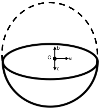
Since gravitational intensity is described as the gravitational force per unit mass at that location, it will also act downward. Thus, the gravitational intensity at the centre of the given hemispherical shell has the direction indicated by the arrow \[c\].
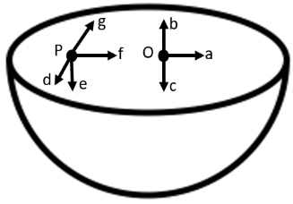
11. Choose the Correct Answer from Among the Given Ones:
For the problem 8.10, the direction of the gravitational intensity at an arbitrary point \[P\] is indicated by the arrow
d,
e,
f,
g.
Ans: Option (ii) is correct.
Gravitational potential (\[V\]) is fixed at all points in a spherical shell. Hence, the potential gravitational gradient \[\left( \frac{dV}{dr} \right)\] is zero everywhere inside the spherical surface.
The potential gravitational gradient is equivalent to the negative of gravitational intensity. Hence, intensity is also zero at all locations inside the spherical shell. This shows that gravitational forces operating at a point in a spherical shell are symmetric.
If the top half of a spherical shell is cut out, then the net gravitational force working on a particle located at centre P will be downward.
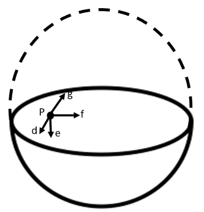
Since gravitational intensity is described as the gravitational force per unit mass at that location, it will also act downward.
Thus, the gravitational intensity at the arbitrary point P of the given hemispherical shell has the direction indicated by the arrow \[e\].
12. A Rocket is Fired from the Earth Towards the Sun. At What Distance from the Earth's Centre is the Gravitational Force on the Rocket Zero?
Mass of the sun\[=2\times {{10}^{30}}kg\], mass of the earth\[=6\times {{10}^{24}}kg\]. Neglect the effect of other planets etc. (orbital radius\[=1.5\times {{10}^{11}}m\]).
Ans: Mass of the Sun, \[{{M}_{s}}=2\times {{10}^{30}}kg\]
Mass of the Earth, \[{{M}_{e}}=6\times {{10}^{24}}kg\]
Orbital radius, \[r=1.5\times {{10}^{11}}m\]
Mass of the rocket=\[m\]
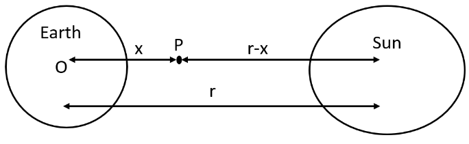
Let \[x\] be the distance from the Earth centre where the gravitational force working on the satellite \[P\] becomes zero.
From Newton's law of gravitation, we can equalize gravitational forces acting on satellite \[P\] under the effect of the Sun and the Earth as:
\[\frac{Gm{{M}_{s}}}{{{\left( r-x \right)}^{2}}}=Gm\frac{{{M}_{e}}}{{{x}^{2}}}\]
We get,
\[{{\left( \frac{r-x}{x} \right)}^{2}}=\frac{{{M}_{s}}}{{{M}_{e}}}\]
\[\Rightarrow \frac{r-x}{x}={{\left( \frac{2\times 1{{0}^{30}}}{60\times {{10}^{24}}} \right)}^{\frac{1}{2}}}=577.35\]
\[\Rightarrow 1.5\times {{10}^{11}}-x=577.35x\]
\[\Rightarrow 578.35x=1.5\times {{10}^{11}}\]
\[\Rightarrow x=\frac{1.5\times {{10}^{11}}}{578.35}=2.59\times {{10}^{8}}m\]
Therefore, \[2.59\times {{10}^{8}}m\] is the distance from the earth's centre at which the gravitational force on the rocket is zero.
13. How will you 'weigh the sun', that is, estimate its mass? The mean orbital radius of the earth around the sun is \[1.5\times {{10}^{8}}km\].
Ans: Orbital radius of the Earth around the Sun, \[r=1.5\times {{10}^{11}}m\].
Time taken by the Earth to cover one revolution around the Sun,
\[T=1\text{ year}\]
\[\Rightarrow \text{T=}365.25\text{ days}\]
We get,
\[\text{T=365}\text{.25}\times \text{24}\times \text{60}\times \text{60}s\]
Universal gravitational constant,
\[G=6.67\times {{10}^{-11}}N{{m}^{2}}k{{g}^{-2}}\].
Thus, we can use the relation given below for calculating the mass of the Sun,
\[M=\frac{4{{\pi }^{2}}{{r}^{3}}}{G{{T}^{2}}}\]
\[\Rightarrow \text{M}=\frac{4\times {{(3.14)}^{2}}\times {{(1.5\times {{10}^{11}})}^{3}}}{6.67\times {{10}^{-11}}\times {{(365.25\times 24\times 60\times 60)}^{2}}}\]
\[\Rightarrow \text{M}=\frac{133.24\times {{10}^{33}}}{6.64\times {{10}^{4}}}\]
\[\Rightarrow \text{M}=2.0\times {{10}^{30}}kg\]
Hence, the mass of the Sun is \[2\times {{10}^{30}}kg\].
14. A Saturn year is \[\mathbf{29}.\mathbf{5}\] times the earth year. How far is Saturn from the sun if the earth is \[1.50\times {{10}^{8}}km\] away from the sun?
Ans: Distance of the Earth from the Sun, \[{{r}_{e}}=1.5\times 1{{0}^{8}}km=1.5\times {{10}^{11}}m\]
Time period of the Earth \[={{T}_{e}}\]
Time period of Saturn, \[{{T}_{s}}=29.5{{T}_{e}}\]
Distance of Saturn from the Sun \[={{r}_{s}}\]
From Kepler's third law of planetary motion, we have,
\[T={{\left( \frac{4{{\pi }^{2}}{{r}^{3}}}{GM} \right)}^{\frac{1}{2}}}\]
For Saturn and Sun, we can write,
\[\frac{{{r}_{s}}^{3}}{{{r}_{e}}^{3}}=\frac{{{T}_{s}}^{2}}{{{T}_{e}}^{2}}\]
\[\Rightarrow {{r}_{s}}={{r}_{e}}{{\left( \frac{{{T}_{s}}}{{{T}_{e}}} \right)}^{\frac{2}{3}}}\]
\[\Rightarrow {{r}_{s}}=1.5\times {{10}^{11}}{{\left( \frac{29.5{{T}_{e}}}{{{T}_{e}}} \right)}^{\frac{2}{3}}}\]
\[\Rightarrow {{r}_{s}}=1.5\times {{10}^{11}}{{(29.5)}^{\frac{2}{3}}}\]
\[\Rightarrow {{r}_{s}}=1.5\times {{10}^{11}}\times 9.55\]
\[\Rightarrow {{r}_{s}}=14.32\times {{10}^{11}}m\]
Hence, the distance between the Sun and Saturn is \[1.43\times {{10}^{12}}m\].
15. A Body weighs \[63N\] on the surface of the earth. What is the gravitational force on it due to the earth at a height equal to half the radius of the Earth?
Ans: Weight of the body, \[W=63N\]
Acceleration due to gravity at height \[h\] from the Earth’s surface
\[{{R}_{e}}=\]Radius of the Earth
For \[h=\frac{{{R}_{e}}}{2}\], gravity at $h$ is given by:
\[{{g}_{h}}=\frac{g}{{{\left( 1+\frac{h}{{{R}_{e}}} \right)}^{2}}}\]
\[\Rightarrow {{g}_{h}}=\frac{g}{{{\left( 1+\frac{1}{2} \right)}^{2}}}\]
\[\Rightarrow {{g}_{h}}=\frac{4}{9}g\]
Weight of a body of mass \[m\] at height \[h\] is given as:
\[W'=m{{g}_{h}}\]
\[\Rightarrow W'=m\times \frac{4}{9}g\]
\[\Rightarrow W'=\frac{4}{9}\times mg\]
\[\Rightarrow \text{W }\!\!'\!\!\text{ }=\frac{4}{9}W\]
\[\Rightarrow \text{W }\!\!'\!\!\text{ }=\frac{4}{9}\times 63\]
\[\Rightarrow W'=28N\]
Thus, the gravitational force on the body due to the earth at a height equal to half the radius of the earth is $28N$.
16. Assuming the Earth to Be a Sphere of Uniform Mass Density, How Much Would a Body Weigh Half Way Down to the Centre of the Earth If it Weighed \[250N\] on the Surface?
Ans: Weight of a body of mass \[m\] at the Earth's surface is given by,
\[W=mg=250N\]
Body of mass \[m\] is located at depth, \[d=\frac{1}{2}{{R}_{e}}\]
Where, \[{{R}_{e}}\] is the radius of the Earth.
Acceleration due to gravity at depth \[{{g}_{d}}\] is given by the relation:
\[{{g}_{d}}=\left( 1-\frac{d}{{{R}_{e}}} \right)g\]
\[\Rightarrow \left( 1-\frac{{{R}_{e}}}{2\times {{R}_{e}}} \right)g=\frac{1}{2}g\]
Weight of the body at depth \[d\],
\[W'=mg\]
\[\Rightarrow W'=m\times \frac{1}{2}g=\frac{1}{2}mg=\frac{1}{2}W\]
\[\Rightarrow W'=\frac{1}{2}\times 250=125N\]
The weight of body half way down to the centre of the earth is $125N.$
17. A Rocket is fired vertically with a speed of \[5km{{s}^{-1}}\] from the earth's surface. How far from the earth does the rocket go before returning to the earth? Mass of the earth\[=6.0\times {{10}^{24}}kg\]; mean radius of the earth\[=6.4\times {{10}^{6}}m;G=6.67\times {{10}^{-11}}N{{m}^{2}}k{{g}^{-2}}\].
Ans: Distance from the centre of the Earth \[=8\times {{10}^{6}}m\]
Velocity of the rocket, \[v=5km{{s}^{-1}}=5\times {{10}^{3}}m{{s}^{-1}}\]
Mass of the Earth, \[{{M}_{e}}=6.0\times {{10}^{24}}kg\]
Radius of the Earth, \[{{R}_{e}}=6.4\times {{10}^{6}}m\]
Height reached by rocket mass $m$, is \[h\].
At the surface of the Earth,
Total energy of the rocket = Kinetic energy + Potential energy
\[=\frac{1}{2}m{{v}^{2}}+\left( \frac{-G{{M}_{e}}m}{{{R}_{e}}} \right)\]
At highest point $h,$ \[v=0\]
And, Potential energy \[=-\frac{G{{M}_{e}}m}{{{R}_{e}}+h}\]
Total energy of the rocket\[=0+\left( \frac{G{{M}_{e}}m}{{{R}_{e}}+h} \right)=-\frac{G{{M}_{e}}m}{{{R}_{e}}+h}\]
From the law of energy conservation, we have
Total energy of the rocket at the Earth's surface = Total energy of rocket at height \[h\].
We have,
\[\frac{1}{2}m{{v}^{2}}+\left( -\frac{G{{M}_{e}}m}{{{R}_{e}}} \right)=-\frac{G{{M}_{e}}m}{{{R}_{e}}+h}\]
\[\Rightarrow \frac{1}{2}{{v}^{2}}=G{{M}_{e}}\left( \frac{1}{{{R}_{e}}}-\frac{1}{{{R}_{e}}+h} \right)\]
\[\Rightarrow \frac{1}{2}{{v}^{2}}=G{{M}_{e}}\left( \frac{{{R}_{e}}+h-{{R}_{e}}}{{{R}_{e}}({{R}_{e}}+h)} \right)\]
\[\Rightarrow \frac{1}{2}{{v}^{2}}=\frac{G{{M}_{e}}h}{{{R}_{e}}({{R}_{e}}+h)}\times \frac{{{R}_{e}}}{{{R}_{e}}}\]
\[\Rightarrow \frac{1}{2}{{v}^{2}}=\frac{g{{R}_{e}}h}{{{R}_{e}}+h}\]
Where, \[g=\frac{GM}{R_{e}^{2}}=9.8m{{s}^{-2}}\] , is the acceleration due to gravity on the Earth’s surface.
Clearly,
\[{{v}^{2}}({{R}_{e}}+h)=2g{{R}_{e}}h\]
\[\Rightarrow {{v}^{2}}{{R}_{e}}=h(2g{{R}_{e}}-{{v}^{2}})\]
\[\Rightarrow h=\frac{{{R}_{e}}{{v}^{2}}}{2g{{R}_{e}}-{{v}^{2}}}\]
\[\Rightarrow \text{h}=\frac{6.4\times 25\times {{10}^{12}}}{100.44\times 1{{0}^{6}}}\]
\[\Rightarrow \text{h}=1.6\times {{10}^{6}}m\]
Height achieved by the rocket with respect to the centre of the Earth, $H$ is given by: \[H={{R}_{e}}+h\]
\[\Rightarrow H=6.4\times {{10}^{6}}+1.6\times {{10}^{6}}\]
We get,
\[H=8.0\times {{10}^{6}}m\]
The distance from the earth is \[8.0\times {{10}^{6}}m\] where the rocket goes before returning to the earth.
18. The escape speed of a projectile on the earth's surface is \[11.2km{{s}^{-1}}\]. A body is projected out with thrice this speed. What is the speed of the body far away from the earth? Ignore the presence of the sun and other planets.
Ans: Projectile’s escape velocity from the Earth, \[{{v}_{esc}}=11.2km{{s}^{-1}}\]
Projection velocity of the projectile, \[{{v}_{p}}={{3}_{{{v}_{esc}}}}\]
Mass of the projectile \[=m\]
Projectile’s velocity far away from the Earth \[={{v}_{f}}\]
Projectile’s total energy on the Earth \[=\frac{1}{2}m{{v}_{p}}^{2}-\frac{1}{2}m{{v}_{esc}}^{2}\]
The projectile's gravitational potential energy far away from the Earth is zero.
Total energy of the projectile far away from the Earth \[=\frac{1}{2}m{{v}_{f}}^{2}\]
From the law of energy conservation, we have
\[\frac{1}{2}m{{v}_{p}}^{2}-\frac{1}{2}m{{v}_{esc}}^{2}=\frac{1}{2}m{{v}_{f}}^{2}\]
We get,
\[{{v}_{f}}=\sqrt{{{v}_{p}}^{2}-{{v}_{esc}}^{2}}\]
\[\Rightarrow {{v}_{f}}=\sqrt{{{(3{{v}_{esc}})}^{2}}-{{({{v}_{esc}})}^{2}}}\]
\[\Rightarrow {{v}_{f}}=\sqrt{8}{{v}_{esc}}\]
\[\Rightarrow {{v}_{f}}=\sqrt{8}\times 11.2\]
\[\Rightarrow {{v}_{f}}=31.68km{{s}^{-1}}\]
Thus, the speed of the body far away from the earth is \[31.68km{{s}^{-1}}\].
19. A Satellite Orbits the Earth at a height of \[400km\] above the surface. How much Energy must be expended to Rocket the Satellite out of the earth's gravitational influence?
Mass of the satellite\[=200kg\];
mass of the earth\[=6.0\times {{10}^{24}}kg\];
radius of the earth\[=6.4\times {{10}^{6}}\]; \[G=6.67\times {{10}^{-11}}N{{m}^{2}}k{{g}^{-2}}\].
Ans: Given that,
Mass of the Earth, \[{{M}_{e}}=6.0\times {{10}^{24}}kg\]
Mass of the satellite, \[m=200kg\]
Radius of the Earth, \[{{R}_{e}}=6.4\times {{10}^{6}}m\]
Universal gravitational constant, \[G=6.67\times {{10}^{-11}}N{{m}^{2}}k{{g}^{-2}}\]
Height of the satellite, \[h=400km=4\times {{10}^{5}}m=0.4\times {{10}^{6}}m\]
Total energy of the satellite at height $h$,
\[TE=\frac{1}{2}m{{v}^{2}}+\left( \frac{-G{{M}_{e}}m}{{{R}_{e}}+h} \right)\]
Orbital velocity of the satellite, \[v=\sqrt{\frac{G{{M}_{e}}}{{{R}_{e}}+h}}\]
Total energy at height $h$, \[TE=\frac{1}{2}m\left( \frac{G{{M}_{e}}}{{{R}_{e}}+h} \right)-\frac{G{{M}_{e}}m}{{{R}_{e}}+h}=-\frac{1}{2}\left( \frac{G{{M}_{e}}m}{{{R}_{e}}+h} \right)\]
The negative sign explains that the satellite is attached to the Earth. This is called the bound energy of the satellite.
The energy needed to send the satellite out of its orbit is equal to the negative of Bound energy.
Bound energy is, \[BE=\frac{1}{2}\left( \frac{G{{M}_{e}}m}{{{R}_{e}}+h} \right)\]
Where, ${{M}_{e}}$ is the mass of the Earth.
${{R}_{e}}$ is the radius of the Earth.
h is the height.
m is the mass of the satellite.
\[\Rightarrow BE=\frac{1}{2}\times \frac{6.67\times {{10}^{-11}}\times 6.0\times {{10}^{24}}\times 200}{\left( 6.4\times {{10}^{6}}+0.4\times {{10}^{6}} \right)}\]
\[\Rightarrow BE=\frac{1}{2}\times \frac{6.67\times 6\times 2\times 10}{6.4\times {{10}^{6}}}\]
\[\Rightarrow BE=5.9\times {{10}^{9}}J\]
Clearly, \[5.9\times {{10}^{9}}J\] energy must be expended to rocket the satellite out of the earth's gravitational influence.
20. Two stars each of one solar mass (\[=2\times {{10}^{30}}kg\]) are approaching each other for a head on collision. When they are a distance \[{{10}^{9}}km\], their speeds are negligible. What is the speed with which they collide? The radius of each star is \[{{10}^{4}}km\]. Assume the stars to remain undistorted until they collide. (Use the known value of \[G\]).
Ans: Mass of each star, \[M=2\times {{10}^{30}}kg\]
Radius of each star, \[R={{10}^{4}}km={{10}^{7}}m\]
Distance between the stars, \[r={{10}^{9}}km={{10}^{12}}m\]
For negligible speeds, \[v=0\]
Total energy of two stars separated at distance \[r\] is given by
\[TE=\frac{-GMM}{r}+\frac{1}{2}m{{v}^{2}}\]
\[\Rightarrow TE=\frac{GMM}{r}+0.\]……(i)
Now, consider the case when the stars are about to collide:
Velocity of the stars \[=v\]
Distance between the centres of the stars \[=2R\]
Total kinetic energy of both stars \[=\frac{1}{2}M{{v}^{2}}+\frac{1}{2}M{{v}^{2}}=M{{v}^{2}}\]
Total potential energy of both stars\[=\frac{-GMM}{2R}\]
Total energy of the two stars \[=M{{v}^{2}}-\frac{GMM}{2R}\]........(ii)
Using the law of conservation of energy, we can write:
\[M{{v}^{2}}-\frac{GMM}{2R}=\frac{-GMM}{R}\]
\[\Rightarrow {{v}^{2}}=\frac{-GM}{r}+\frac{GM}{2r}=GM\left( -\frac{1}{r}+\frac{1}{2R} \right)\]
\[\Rightarrow {{v}^{2}}=6.67\times 1{{0}^{-10}}\times 2\times {{10}^{30}}\left[ -\frac{1}{{{10}^{12}}}+\frac{1}{2\times {{10}^{7}}} \right]\]
\[\Rightarrow {{v}^{2}}=13.34\times {{10}^{19}}\left[ -{{10}^{-12}}+5\times {{10}^{-8}} \right]\]
\[\Rightarrow {{v}^{2}}\sim 13.34\times {{10}^{19}}\times 5\times {{10}^{-8}}\]
\[\Rightarrow {{v}^{2}}\sim 6.67\times {{10}^{12}}\]
\[\Rightarrow v=\sqrt{6.67\times {{10}^{12}}}\]
\[\Rightarrow v=2.58\times {{10}^{6}}m/s\]
The speed with which the two stars collide is \[2.58\times {{10}^{6}}m/s\].
21. Two heavy spheres each of mass \[100kg\] and radius \[0.10m\] are placed \[1.0m\] apart on a horizontal table. What is the gravitational force and potential at the midpoint of the line joining the centres of the spheres? Is an object placed at that point in equilibrium? If so, is the equilibrium stable or unstable?
Ans: The situation is represented in the given figure:
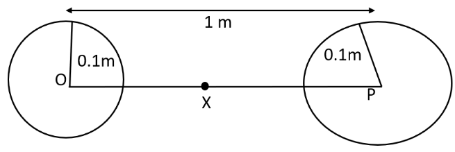
Mass of each sphere, \[M=100kg\]
Separation between the spheres, \[r=1m\]
\[X\] is the midpoint between the spheres. Gravitational force at point \[X\] will be zero. This is because the gravitational force applied by each sphere will act in opposite directions.
Gravitational potential at point \[X\]\[=\frac{-GM}{\left( \frac{r}{2} \right)}-\frac{GM}{\left( \frac{r}{2} \right)}\]
\[\Rightarrow PE=-4\frac{GM}{r}\]
\[\Rightarrow PE=\frac{4\times 6.67\times {{10}^{-11}}\times 100}{r}\]
\[\Rightarrow PE=-2.67\times {{10}^{-8}}J/kg\]
Any object placed at point \[X\] will be in equilibrium state, but the equilibrium is unstable. This is because any change in the position of the object will vary the effective force in that direction.
22. As you have learnt in the text, a geostationary satellite orbits the earth at a height of nearly \[36,000km\] from the surface of the earth. What is the potential due to earth's gravity at the site of this satellite? (Take the potential energy at infinity to be zero).
Mass of the Earth = \[6.0\times {{10}^{24}}kg\],
Radius = \[6400km.\]
Ans: Mass of the Earth, \[M=6.0\times {{10}^{24}}kg\]
Radius of the Earth, \[R=6400km=6.4\times {{10}^{6}}m\]
Height of a geostationary satellite from the surface of the Earth,
\[h=36000km=3.6\times {{10}^{7}}m\]
Gravitational potential energy due to Earth’s gravity at height \[h\],
\[PE=\frac{-GM}{(R+h)}\]
\[\Rightarrow PE=-\frac{6.67\times 1{{0}^{-11}}\times 6.0\times {{10}^{24}}}{3.6\times {{10}^{7}}+0.64\times {{10}^{7}}}\]
\[\Rightarrow PE=-\frac{6.67\times 6}{4.24}\times {{10}^{13-7}}\]
\[\Rightarrow PE=-9.4\times {{10}^{6}}Jk{{g}^{-1}}\]
The potential energy due to earth's gravity at the site of this satellite is \[-9.4\times {{10}^{6}}Jk{{g}^{-1}}\].
23. A star 2.5 times the mass of the sun and collapsed to a size of \[12km\] rotates with a speed of \[1.2\] evolutions per second. (Extremely compact stars of this kind are known as neutron stars. Certain stellar objects called pulsars belong to this category). Will an object placed on its equator remain stuck to its surface due to gravity? (Mass of the sun\[=2\times {{10}^{30}}kg\]).
Ans: Yes.
A body gets held to the star's surface if the inward gravitational force is larger than the outward centrifugal force generated by the star's rotation.
Gravitational force,
\[{{f}_{g}}=\frac{GMm}{{{R}^{2}}}\]
Where, M is mass of the star, \[M=2.5\times 2\times {{10}^{30}}=5\times {{10}^{30}}kg\]
m is the mass of the body
R is the radius of star, \[\text{R}=12km=1.2\times {{10}^{4}}m\]
\[\therefore {{f}_{g}}=\frac{6.67\times {{10}^{-11}}\times 5\times {{10}^{30}}\times m}{{{(1.2\times {{10}^{4}})}^{2}}}\]
\[{{f}_{g}}=2.31\times {{10}^{11}}mN\]
Centrifugal force, \[{{f}_{c}}=mr{{\omega }^{2}}\]
\[\omega =\text{Angular speed}=2\pi v\]
\[v=\text{Angular frequency}=1.2rev\text{ }{{s}^{-1}}\]
\[{{f}_{c}}=mR{{(2\pi v)}^{2}}\]
\[\Rightarrow {{f}_{c}}=m\times (1.2\times {{10}^{4}})\times 4\times {{(3.14)}^{2}}\times {{(1.2)}^{2}}\]
\[\Rightarrow {{f}_{c}}=1.7\times {{10}^{5}}mN\]
Since \[{{f}_{g}}>{{f}_{c}}\], the body will remain held to the surface of the star.
24. A Spaceship is Stationed on Mars. How Much Energy Must Be Expended on the Spaceship to Launch it Out of the Solar System?
Mass of the spaceship\[=1000kg\]; mass of the Sun\[=2\times {{10}^{30}}kg\];
mass of mars\[=6.4\times {{10}^{23}}kg\]; radius of mars\[=3395km\];
radius of the orbit of mars\[=2.28\times {{10}^{8}}kg;G=6.67\times {{10}^{-11}}{{m}^{2}}k{{g}^{-2}}\].
Ans: Mass of the spaceship, \[{{m}_{s}}=1000kg\]
Mass of the Sun, \[M=2\times 1{{0}^{30}}kg\]
Mass of Mars, \[{{M}_{m}}=6.4\times {{10}^{23}}kg\]
Orbital radius of Mars, \[R=2.28\times {{10}^{8}}kg=2.28\times {{10}^{11}}m\]
Radius of Mars, \[r=3395km=3.395\times {{10}^{6}}m\]
Universal gravitational constant, \[G=6.67\times {{10}^{-11}}{{m}^{2}}k{{g}^{-2}}\]
Potential energy of the spaceship due to the gravitational attraction of the Sun\[=\frac{-GM{{m}_{s}}}{R}\]
Potential energy of the spaceship due to the gravitational attraction of Mars\[=\frac{-G{{M}_{m}}{{m}_{s}}}{r}\]
Since the spaceship is stationed on Mars, its velocity and hence, its kinetic energy will be zero.
Total energy of the spaceship \[=\frac{-GM{{m}_{s}}}{R}-\frac{G{{M}_{m}}{{m}_{s}}}{r}\]
\[TE=-G{{m}_{s}}\left( \frac{M}{R}+\frac{{{M}_{m}}}{r} \right)\]
The negative sign indicates that the system is in a bound state.
Energy required for launching the spaceship out of the solar system = – (Total energy of the spaceship)
We have,
\[E=G{{m}_{s}}\left( \frac{M}{R}+\frac{{{m}_{m}}}{r} \right)\]
\[\Rightarrow E=6.67\times 1{{0}^{-11}}\times {{10}^{3}}\times \left( \frac{2\times {{10}^{30}}}{2.28\times {{10}^{11}}}+\frac{6.4\times {{10}^{23}}}{3.395\times {{10}^{5}}} \right)\]
\[\Rightarrow E=6.67\times {{10}^{-8}}\left( 87.72\times {{10}^{17}}+1.88\times {{10}^{17}} \right)\]
\[\Rightarrow E=6.67\times {{10}^{-8}}\times 1.88\times {{10}^{17}}\]
\[\Rightarrow E=596.97\times {{10}^{9}}\]
\[\Rightarrow E=6\times {{10}^{11}}J\]
The required energy for the spaceship to launch it out of the solar system is \[6\times {{10}^{11}}J\].
25. A rocket is fired 'vertically' from the surface of mars with a speed of \[2km/s\]. If \[20%\] of its initial energy is lost due to Martian atmospheric resistance, how far will the rocket go from the surface of mars before returning to it? Mass of mars\[=6.4\times {{10}^{23}}kg\]; radius of mars\[=3395km\];\[G=6.67\times {{10}^{-11}}N{{m}^{2}}k{{g}^{-2}}\].
Ans: Initial velocity of the rocket, \[v=2km/s=2\times {{10}^{3}}m/s\]
Mass of Mars, \[M=6.4\times {{10}^{23}}kg\]
Radius of Mars, \[R=3395km=3.395\times {{10}^{6}}m\]
Universal gravitational constant, \[G=6.67\times {{10}^{-11}}N{{m}^{2}}k{{g}^{-2}}\]
Mass of the rocket\[=m\]
Initial kinetic energy of the rocket \[=\frac{1}{2}m{{v}^{2}}\]
Initial potential energy of the rocket \[=\frac{-GMm}{R}\]
Total initial energy \[=\frac{1}{2}m{{v}^{2}}-\frac{GMm}{R}\]
If \[20%\] of initial kinetic energy is lost due to Martian atmospheric resistance, then it shows only \[80%\] of its kinetic energy helps in reaching a height.
Total initial energy available, \[TE=\frac{80}{100}\times \frac{1}{2}m{{v}^{2}}-\frac{GMm}{R}\]
\[TE=0.4m{{v}^{2}}-\frac{GMm}{R}\]
Maximum height reached by the rocket\[=h\]
At this height, the velocity and hence, the kinetic energy of the rocket will become zero.
Total energy of the rocket at height $h,$ \[=-\frac{GMm}{\left( R+h \right)}\]
Applying the law of energy conservation for the rocket, we can write:
\[0.4m{{v}^{2}}-\frac{GMm}{R}=\frac{-GMm}{\left( R+h \right)}\]
\[\Rightarrow 0.4{{v}^{2}}=\frac{GM}{R}-\frac{GM}{R+h}\]
\[\Rightarrow 0.4{{v}^{2}}=GM\left( \frac{1}{R}-\frac{1}{R+h} \right)\]
\[\Rightarrow 0.4{{v}^{2}}=GM\left( \frac{R+h-R}{R\left( R+h \right)} \right)\]
After solving further, we get
\[0.4{{v}^{2}}=\frac{GMh}{R\left( R+h \right)}\]
\[\Rightarrow \frac{R+h}{h}=\frac{GM}{0.4{{v}^{2}}R}\]
\[\Rightarrow \frac{R}{h}+1=\frac{GM}{0.4{{v}^{2}}R}\]
\[\Rightarrow \frac{R}{h}=\frac{GM}{0.4{{v}^{2}}R}-1\]
\[\Rightarrow h=\frac{R}{\frac{GM}{0.4{{v}^{2}}R}-1}\]
\[\Rightarrow h=\frac{0.4{{R}^{2}}{{v}^{2}}}{GM-0.4{{v}^{2}}R}\]
Putting all the values, we get,
\[h=\frac{0.4\times {{\left( 3.395\times {{10}^{6}} \right)}^{2}}\times {{\left( 2\times {{10}^{3}} \right)}^{2}}}{6.67\times 1{{0}^{-11}}\times 6.4\times {{10}^{23}}-0.4\times {{\left( 2\times {{10}^{3}} \right)}^{2}}\times \left( 3.395\times {{10}^{6}} \right)}\]
\[\Rightarrow h=\frac{18.442\times {{10}^{18}}}{42.688\times {{10}^{12}}-53432\times {{10}^{12}}}\]
\[\Rightarrow h=\frac{18.442}{37.256}\times {{10}^{6}}\]
\[\Rightarrow h=495\times {{10}^{3}}m\]
\[\Rightarrow h=495km\]
So, the height attained by the rocket from the surface will be $495km$.
Gravitation Chapter at a Glance - Class 11 NCERT Solutions Summary
Introduction
Gravity is the force of attraction exerted by earth towards is centre on a body lying on or near the surface of earth. Gravity is merely a special case of gravitation and is also called earth’s gravitational pull. Weight of a body is defined as the force of attraction exerted by the earth on the body towards its centre. The units and dimensions of gravity pull or weight are the same as those of force.
Newton’s Law of Gravitation
Definition
Every particle attracts every other particle with a force which is directly proportional to the product of their masses and inversely proportional to the square of the distance between them.

Mathematical Form
If m1 and m2 are the masses of the particles and r is the distance between them, the force of attraction F between the particles is given by
$F\alpha\frac{m_{1}m_{2}}{r^{2}}$
$\therefore F=G \frac{m_{1}m_{2}}{r^{2}}$
Where G is the universal constant of gravitation.
Universal gravitational constant is measured in N m2/kg2
The dimensional formula is (L3M-1T-2)universal gravitational constant
The value of G is: 6.67408x10⁻¹¹Nm2/kg2
Acceleration Due to Gravity
Definition
Acceleration due to gravity is the acceleration gained by a an object due to
gravitational force. It SI unit is m/s2 . It has both magnitude direction, hence, it is a vector quantity.
Acceleration due to gravity is represented by g.
The stranded value of g on the surface of earth at sea level is 9.8m/s2
The Acceleration Due to Gravity at a Height h above the Earth’s Surface
$g_{h}=g\left ( \frac{R+h}{R} \right )^{-2}$
$g_{h}=g\left ( 1+\frac{h}{R} \right )^{-2}$
If h << R, then neglecting high power’s of ‘h’ we get,
$g_{h}=g\left ( 1-\frac{2h}{R} \right )$
Effect of Depth on a Acceleration due to Gravity
$g_{d}=g\left ( 1-\frac{d}{R} \right )$
Variation of ‘g’ with Latitude due to Rotational Motion of Earth
Due to the rotational of the earth the force \[mr\omega ^{2}cos\lambda\] radially outwards. Hence the net force of attraction exerted by the earth of the particle and directed towards the centre of the earth is given by \[mg{}'=mg-mr\omega ^{2}cos\lambda\] where \[g{}'\]is the value of the acceleration due to gravity at the point P.
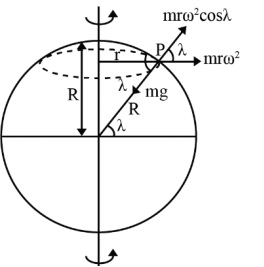
$\therefore g{}'=g-r\omega ^{2}cos\lambda$
Now, $r=R cos \lambda$ (where R is the radius of the earth)
Then $g{}'=g - (R cos \lambda )\omega ^{2}cos\lambda$
$\therefore g{}'=g-r\omega ^{2}cos\lambda$
The effective acceleration due to gravity at a point ‘P’ is given by,
$ g{}'=g-r\omega ^{2}cos\lambda$
Thus value of ‘g’ changes with $\lambda$ and $\omega$
At Poles,
$\lambda = 90^{\circ}$
$g{}'=g-r\omega ^{2}cos^{2} 90^{\circ}$
$ g{}'=g$
This is maximum acceleration due to gravity.
At Equator
$\lambda = 0$
$g{}'=g-r\omega ^{2}cos^{2} 0$
$g{}'=g-R\omega ^{2}$
This is minimum acceleration due to gravity. Variation due to shape.
Gravitation Field and Gravitation Potential
Gravitational Field
The space surrounding the body within which its gravitational force of attraction is experienced by other bodies is called gravitational field.
$g{}'=g-R\omega ^{2}$
The unit of the intensity of gravitational field is N kg-1. Intensity of gravitational field due to point mass:
$E=\frac{F}{m^{\circ}}\Rightarrow E = \frac{GM}{r^{2}}$
Dimensional formula of intensity of gravitational field
$=\frac{F}{m}=\left [ \frac{MLT^{-2}}{M} \right ] = M^{0}LT^{-2}$
Gravitational Potential
The gravitational potential at any point in a gravitational field is defined as the work done to bring a unit mass slowly from infinity to that point.
1. The gravitational potential (V) at a point at distance r from a point mass M is given by,
$V = - \dfrac{GM}{r}$ (Where G is the constant of gravitation)
Gravitational Potential Energy
Gravitational potential energy of a body at a point is defined as the work done in slowly bringing the body from infinity to that point.
Let a body of mass m is displaced through a distance ‘dr’ towards the mass M, then work done given by,
$dW=Fdr=\frac{GMm}{r^{2}}dr\Rightarrow \int dW=\int_{\infty}^{r}\frac{GMm}{r^{2}}dr$
Gravitational potential energy,
$U = -\frac{GMm}{r}$
Escape Velocity of a Body
Expression for the Escape Velocity of A Body at Rest on the Earth’s Surface
The minimum velocity with which a body should be projected from the surface of the earth, so that it escapes from the earth’s gravitational field, is called the escape velocity. Thus, if a body or a satellite is given the escape velocity, its kinetic energy of projection will be equal to its binding energy.
Kinetic Energy of projection = Binding Energy.
$\therefore \frac{1}{2}mv_{c}^{2}=\frac{GMm}{R}$
$\therefore v_{c}= \sqrt{\frac{2GM}{R}}$
Satellite
Definition
Any smaller body which revolves around another larer body under the influence of its gravitation is called a satellite. The satellite may be natural or artificial.
Orbital Velocity
The horizontal velocity with which a satellite must be projected from a point above the earth’s surface, so that it revolves in a circular orbit round the earth, is called the orbital velocity of the satellite.
Suppose that a satellite of mass m is raised to a height h above the earth’s surface and then projected in a horizontal direction with the orbital velocity $v_{o}$. The satellite begins to move round the earth in a circular orbit of radius, R + h, where R is the radius of the earth.
The gravitational force acting on the satellite is ${\frac{GMm}{\left ( R+h \right )^{2}}}$, where M is the mass of the earth and G is the constant of gravitation.
For circular motion,
$\frac{mv_{0}^{2}}{\left ( R+h \right )}=\frac{GMm}{\left ( R+h \right )^{2}}$
$\therefore v_{0}= \sqrt{\frac{GM}{\left ( R+h \right )}}$
Period of Revolution of a Satellite
The time taken by a satellite to complete one revolution round the earth is called its period or periodic time (T).
$T=2\pi \sqrt{\frac{r^{3}}{GM}}$
Kepler’s Laws
Law of Orbit
Each Planet moves around the sun in an elliptical orbit with the sun at one of the foci as shown in figure. The eccentricity of an ellipse is defined as the ratio of the distance SO and AO i.e. $e=\frac{SO}{AO}$
$\therefore e=\frac{SO}{a}, SO=ea$

The distance of closest approach with sun at F1 is AS. This position is called perigee. The greatest distance (BS) of the planet from the sun is at position B apogee.
At, Perigee (AS) = AO – OS = a – ea = a (1 – e)
At, apogee (BS) = OB + OS = a + ea = a (1 + e)
Law of Area
The line joining the sun and a planet sweeps out equal areas in equal intervals of time. A planet takes the same time to travel from A to B as from C to D as shown in figure. (The shaded areas are equal). Naturally the planet has to move faster between C to D.
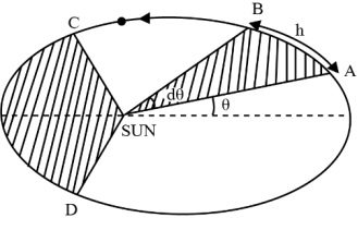
Areal Velocity $= \frac{area\;swept}{time}$
$=\frac{\frac{1}{2}r\left ( rd\Theta \right )}{dt}=\frac{1}{2}r^{2}\frac{d\Theta }{dt}=\frac{1}{2}\frac{mr^{2}\omega }{m}=\frac{L}{2m}$
Hence $\frac{L}{2m}$ = constant. [As L = constant]
Law of Periods
The square of the time for the planet to complete a revolution about the sun is proportional to the cube of semimajor axis of the elliptical orbit.
$T^{2}\alpha a^{3}$
Overview of Deleted Syllabus for CBSE Class 11 Physics Gravitation
Conclusion
NCERT for Gravitation Class 11 Solutions Physics by Vedantu explores the universal force of gravity that affects all objects with mass. This Chapter provides an in-depth exploration of the principles governing gravitational forces and their effects on motion. By mastering these concepts, students gain understanding of the universe's workings, from terrestrial phenomena to celestial mechanics. This chapter builds on the concepts of classical mechanics to explain how gravitational forces operate across the universe. In previous years' exams, around 3-4, questions were asked from the chapter's Gravitation. Consistent practice and a thorough understanding of these topics are essential for performing well in exams.
Other Study Material for CBSE Class 11 Physics Chapter 7
Chapter-Specific NCERT Solutions for Class 11 Physics
Given below are the chapter-wise NCERT Solutions for Class 11 Physics. Go through these chapter-wise solutions to be thoroughly familiar with the concepts.
CBSE Class 11 Physics Study Materials
