


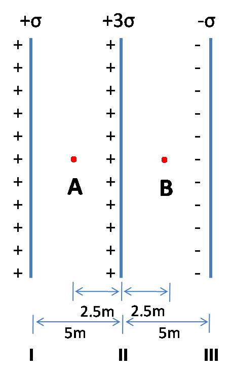
The figure shows three infinite non-conducting plates of charge perpendicular to the plane of the paper with charge per unit area \[ + \sigma , + 3\sigma \] and$ - \sigma $. The ratio of the net electric field at the point A to the point B is$1/x$ . Find x.
Answer
273.9k+ views
Hint: To solve this problem, first we need to find out the net electric fields at the points A and B. For that, we may use the equation for the electric field at a point near to an infinite non-conducting plate having a given charge density, $E = \dfrac{\sigma }{{2\varepsilon 0}}$. The net electric fields at both the points can be calculated by adding the individual electric fields due to each of the infinite non-conducting plates.
Formula used: Here we use the equation which can be derived from Gauss law: $E = \dfrac{\sigma }{{2\varepsilon 0}}$where $E$ is the electric field, $\sigma $ is the surface charge density or charge per unit area of the infinite non-conducting plate, and $\varepsilon 0$ is the permittivity of free space.
Complete step-by-step answer:
As we all can understand from the figure, it is clear that the net electric field at point A has contributions of the fields due to the plates I, II and III. The figure clearly describes that the surface charge densities of the plates I, II and III are $ + \sigma , + 3\sigma $and $ - \sigma $ respectively. Now, the electric field at point A due to the plate I would be:
\[EA\left( I \right) = \dfrac{{ - \sigma }}{{2\varepsilon 0}}\]
Similarly, the electric field at A due to the plates II and II are:
\[
EA\left( {II} \right) = \dfrac{{3\sigma }}{{2\varepsilon 0}} \\
EA\left( {III} \right) = \dfrac{{ - \sigma }}{{2\varepsilon 0}} \\
\]
respectively. Now, the net electric field at A is given by:
\[
EA = EA\left( I \right) + EA\left( {II} \right) + EA\left( {III} \right) \\
\Rightarrow EA = \dfrac{{ - \sigma }}{{2\varepsilon 0}} + \dfrac{{3\sigma }}{{2\varepsilon 0}} + \dfrac{{ - \sigma }}{{2\varepsilon 0}} = \dfrac{\sigma }{{2\varepsilon 0}} \\
\]
Similarly the electric fields at point B due to the three plates are given by:
\[
EB\left( I \right) = \dfrac{{ - \sigma }}{{2\varepsilon 0}} \\
EB\left( {II} \right) = \dfrac{{ - 3\sigma }}{{2\varepsilon 0}}and \\
EB\left( {III} \right) = \dfrac{{ - \sigma }}{{2\varepsilon 0}} \\
\]
Thus, the net electric field at the point B can be estimated as:
\[
EB = EB\left( I \right) + EB\left( {II} \right) + EB\left( {III} \right) \\
\Rightarrow EA = \dfrac{{ - \sigma }}{{2\varepsilon 0}} + \dfrac{{ - 3\sigma }}{{2\varepsilon 0}} + \dfrac{{ - \sigma }}{{2\varepsilon 0}} = \dfrac{{ - 5\sigma }}{{2\varepsilon 0}} \\
\]
Finally, the ratio of the net electric field at point A to that at point B
\[\left| {\dfrac{{EA}}{{EB}}} \right| = \dfrac{\sigma }{{2\varepsilon 0}} \div \dfrac{{5\sigma }}{{2\varepsilon 0}} = \dfrac{\sigma }{{2\varepsilon 0}} \times \dfrac{{2\varepsilon 0}}{{5\sigma }} = \dfrac{1}{5}\]
So, as we found that the ratio of the net electric fields at both the points is $\dfrac{1}{5}$, the value of $x = 5$.
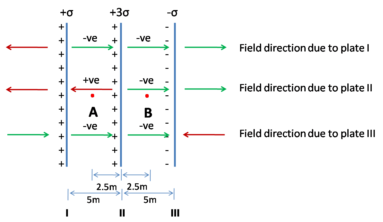
Note: When we are performing the calculation of the individual electric fields at both the points due to each of the non-conducting plates, we may sometimes end up in making the mistake of putting a wrong polarity. So, it is important to keep in mind that the electric field lines travel away from the positive plates while they travel towards the negative plates, shown in the illustration below. If we give the polarity of the field at a point depending on the direction of the field lines and then do the summation, the problem can be solved very easily.
Formula used: Here we use the equation which can be derived from Gauss law: $E = \dfrac{\sigma }{{2\varepsilon 0}}$where $E$ is the electric field, $\sigma $ is the surface charge density or charge per unit area of the infinite non-conducting plate, and $\varepsilon 0$ is the permittivity of free space.
Complete step-by-step answer:
As we all can understand from the figure, it is clear that the net electric field at point A has contributions of the fields due to the plates I, II and III. The figure clearly describes that the surface charge densities of the plates I, II and III are $ + \sigma , + 3\sigma $and $ - \sigma $ respectively. Now, the electric field at point A due to the plate I would be:
\[EA\left( I \right) = \dfrac{{ - \sigma }}{{2\varepsilon 0}}\]
Similarly, the electric field at A due to the plates II and II are:
\[
EA\left( {II} \right) = \dfrac{{3\sigma }}{{2\varepsilon 0}} \\
EA\left( {III} \right) = \dfrac{{ - \sigma }}{{2\varepsilon 0}} \\
\]
respectively. Now, the net electric field at A is given by:
\[
EA = EA\left( I \right) + EA\left( {II} \right) + EA\left( {III} \right) \\
\Rightarrow EA = \dfrac{{ - \sigma }}{{2\varepsilon 0}} + \dfrac{{3\sigma }}{{2\varepsilon 0}} + \dfrac{{ - \sigma }}{{2\varepsilon 0}} = \dfrac{\sigma }{{2\varepsilon 0}} \\
\]
Similarly the electric fields at point B due to the three plates are given by:
\[
EB\left( I \right) = \dfrac{{ - \sigma }}{{2\varepsilon 0}} \\
EB\left( {II} \right) = \dfrac{{ - 3\sigma }}{{2\varepsilon 0}}and \\
EB\left( {III} \right) = \dfrac{{ - \sigma }}{{2\varepsilon 0}} \\
\]
Thus, the net electric field at the point B can be estimated as:
\[
EB = EB\left( I \right) + EB\left( {II} \right) + EB\left( {III} \right) \\
\Rightarrow EA = \dfrac{{ - \sigma }}{{2\varepsilon 0}} + \dfrac{{ - 3\sigma }}{{2\varepsilon 0}} + \dfrac{{ - \sigma }}{{2\varepsilon 0}} = \dfrac{{ - 5\sigma }}{{2\varepsilon 0}} \\
\]
Finally, the ratio of the net electric field at point A to that at point B
\[\left| {\dfrac{{EA}}{{EB}}} \right| = \dfrac{\sigma }{{2\varepsilon 0}} \div \dfrac{{5\sigma }}{{2\varepsilon 0}} = \dfrac{\sigma }{{2\varepsilon 0}} \times \dfrac{{2\varepsilon 0}}{{5\sigma }} = \dfrac{1}{5}\]
So, as we found that the ratio of the net electric fields at both the points is $\dfrac{1}{5}$, the value of $x = 5$.
Note: When we are performing the calculation of the individual electric fields at both the points due to each of the non-conducting plates, we may sometimes end up in making the mistake of putting a wrong polarity. So, it is important to keep in mind that the electric field lines travel away from the positive plates while they travel towards the negative plates, shown in the illustration below. If we give the polarity of the field at a point depending on the direction of the field lines and then do the summation, the problem can be solved very easily.
Recently Updated Pages
Wheatstone Bridge – Principle, Formula, Diagram & Applications
Mass vs Weight: Key Differences Explained for Students
Circuit Switching vs Packet Switching: Key Differences Explained
Uniform Acceleration Explained: Formula, Examples & Graphs
Young’s Double Slit Experiment Derivation Explained
Classification of Drugs in Chemistry: Types, Examples & Exam Guide
Trending doubts
JEE Main 2026: Exam Dates, Session 2 Updates, City Slip, Admit Card & Latest News
JEE Main Participating Colleges 2026 - A Complete List of Top Colleges
Kinematics Mock Test for JEE Main 2025-26: Comprehensive Practice
Understanding the Electric Field of a Uniformly Charged Ring
Understanding Atomic Structure for Beginners
Derivation of Equation of Trajectory Explained for Students
Other Pages
CBSE Class 12 Physics Question Paper 2026: Download SET-wise PDF with Answer Key & Analysis
JEE Advanced 2026 Notification Out with Exam Date, Registration (Extended), Syllabus and More
JEE Advanced Percentile vs Marks 2026: JEE Main Cutoff, AIR & IIT Admission Guide
JEE Advanced Weightage Chapter Wise 2026 for Physics, Chemistry, and Mathematics
How to Convert a Galvanometer into an Ammeter or Voltmeter
Electron Gain Enthalpy and Electron Affinity Explained