


Essential Techniques for Analyzing Electrical Circuits
Understanding how to solve any electric circuit is a fundamental requirement for mastering JEE Main Physics. Electric circuits involve the analysis of components such as resistors, sources, and connections, with a focus on determining current, voltage, or resistance using systematic laws and methods.
Definition and Classification of Electric Circuits
An electric circuit is a closed path through which electric current flows. The primary types include open circuits, closed circuits, DC circuits, AC circuits, series circuits, parallel circuits, and series-parallel circuits, distinguished by how the elements are connected and the nature of current flow.
A closed circuit allows uninterrupted current flow, whereas an open circuit prevents current due to a break in connectivity. DC circuits carry unidirectional current, while AC circuits have current that varies periodically in direction and magnitude.
Series circuits connect components sequentially, ensuring the same current flows through each element. In parallel circuits, components are connected across the same two nodes, resulting in voltage equality but divided currents. Series-parallel circuits combine both series and parallel arrangements.
Representation of Series and Parallel Resistances
When multiple resistors are joined in series, the total or equivalent resistance is the sum of individual resistances. This principle is essential for simplifying series circuits analytically.
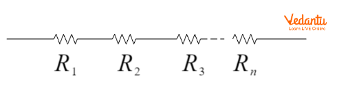
In series, the equivalent resistance is represented as $R_{\text{series}} = R_1 + R_2 + R_3 + ... + R_n$. This method is applied before using further circuit analysis tools, and more details can be found in Understanding Electrical Resistance.
For resistors in parallel, the reciprocal of the total resistance equals the sum of the reciprocals of each resistance, allowing stepwise reduction of parallel sections for easier circuit evaluation.
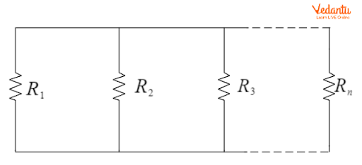
The equivalent parallel resistance formula is $\dfrac{1}{R_{\text{parallel}}} = \dfrac{1}{R_1} + \dfrac{1}{R_2} + \dfrac{1}{R_3} + ... + \dfrac{1}{R_n}$. Application of this rule is foundational before proceeding to more advanced analysis.
Ohm’s Law in Circuit Analysis
Ohm’s Law relates voltage (V), current (I), and resistance (R) in an electric circuit. It states that, with constant temperature, the potential difference across a resistor is directly proportional to the current through it.

Mathematically, Ohm’s Law is $V = I R$. This fundamental relation is essential to analyze both simple and combination circuits and is discussed with more depth in Ohm's Law and Resistance.
Kirchhoff’s Laws for Any Electric Circuit
For complex circuits containing multiple loops or branches, Ohm’s Law alone is insufficient. Kirchhoff’s Current Law (KCL) and Kirchhoff’s Voltage Law (KVL) systematically enable circuit resolution, regardless of complexity.
Kirchhoff’s Current Law (KCL) states that the algebraic sum of currents entering a junction is zero, ensuring conservation of electric charge at every node in the network.
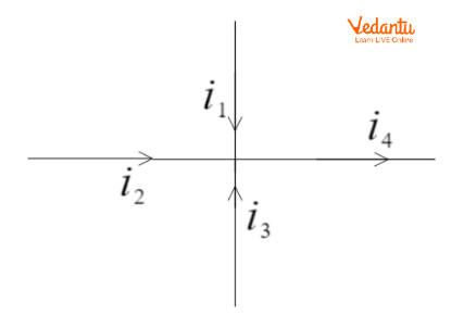
Applying KCL: $\sum I = 0$, where incoming currents are positive and outgoing currents are negative. Every node must satisfy KCL in any electric circuit problem.
Kirchhoff’s Voltage Law (KVL) dictates that the algebraic sum of all potential differences in a closed circuit loop is zero, embodying conservation of energy for any electric circuit.

A loop equation based on KVL can be written as $V_1 - V_2 - IR_1 - IR_2 = 0$, or in a simple circuit $V = IR$. These laws together allow for a systematic solution of any electric circuit.
Standard Procedure for Solving Electric Circuit Problems
To solve an electric circuit, first simplify series and parallel resistor combinations. Apply Ohm’s Law where applicable to determine unknowns such as currents and voltages.
Assign symbols to each current, voltage, and node in the circuit. Use KCL at each junction and KVL around all independent loops to form linear equations.
For circuits with multiple sources, the superposition theorem states the response in any element equals the sum of responses from each source acting alone, with others replaced by their internal resistances. For a deep understanding of superposition and other methods, refer to Circuit Solving Techniques.
Tabular Overview: Series and Parallel Resistances
| Connection Type | Equivalent Resistance |
|---|---|
| Series | $R = R_1 + R_2 + ... + R_n$ |
| Parallel | $\dfrac{1}{R} = \dfrac{1}{R_1} + \dfrac{1}{R_2} + ... + \dfrac{1}{R_n}$ |
Worked Examples in Circuit Solving
Example 1: Three identical resistors each of resistance $R$ consume $100$ W in series. When connected in parallel, power consumed is $P = 9 \times 100 = 900$ W, illustrating how power varies with different configurations.
Example 2: A wire with resistance $200\ \Omega$ is reshaped to a wire with one-fourth the original radius. Since $R \propto \dfrac{1}{(\text{radius})^2}$, the new resistance is $R' = 16 \times 200 = 3200\ \Omega$.
Strategies for Solving Complex Circuits
- Identify and label all nodes and branches
- Simplify resistors using series/parallel laws
- Formulate KCL at each node
- Apply KVL in all loops
- Solve the system of equations algebraically
- Validate with power and energy checks
Capacitors and inductors follow analogous rules, with series and parallel combination rules for capacitance and inductance in AC and DC circuits. For circuits with capacitors or inductors, RC Circuit Analysis provides further insights.
Key Points to Avoid and Fixing Circuit Issues
- Check for open or broken connections before analysis
- Verify if resistors are overloaded to prevent damage
- Inspect for short circuits causing excessive current flow
- Ensure circuit breakers function for safety and analysis
Fixing issues such as open circuits, short circuits, or overloaded components requires systematic analysis of connections, current paths, and device ratings. These practices prevent circuit faults and facilitate efficient troubleshooting.
Conceptual clarity in electric circuit analysis is supported by applying definitions, using laws systematically, and practicing with challenging questions. Foundational skills in circuit solving also reinforce other areas in physics, such as Basics of Kinematics and Kinetic Energy of Rotating Bodies.
FAQs on Simple Steps to Solve Any Electric Circuit
1. How do you solve any electric circuit step by step?
Solving any electric circuit involves following a structured approach to analyze voltage, current, and resistance. To solve any electric circuit step by step:
- Identify and label all circuit elements (resistors, batteries, switches, etc.)
- Redraw the circuit clearly if needed
- Apply Ohm’s Law (V=IR) where relevant
- Use Kirchhoff’s Laws:
- Kirchhoff’s Current Law (KCL): Sum of currents at a junction is zero
- Kirchhoff’s Voltage Law (KVL): Sum of voltages in a loop is zero
- Simplify series and parallel resistances
- Solve the equations algebraically
- Check your answers for consistency and units
2. What are the basic rules to solve electric circuits?
The basic rules to solve electric circuits include Ohm’s law, Kirchhoff’s laws, and simple reduction techniques.
- Ohm’s Law: V = I × R
- Kirchhoff’s Current Law (KCL): Total incoming current equals total outgoing current at any node
- Kirchhoff’s Voltage Law (KVL): The algebraic sum of all voltages in a closed loop is zero
- Combine resistors in series and parallel as needed
- Label all currents and voltages properly
3. How do you solve a series and parallel circuit?
To solve a series and parallel circuit, first identify which resistors are in series and which are in parallel, then simplify step by step.
- For series circuits:
- Add resistances (R_total = R1 + R2 +...)
- For parallel circuits:
- Use 1/R_total = 1/R1 + 1/R2 + ...
- Solve for total resistance
- Use Ohm’s Law to find current and voltage
4. What is the first step in analyzing an electric circuit?
The first step in analyzing an electric circuit is to carefully identify and label all components and their values.
- Draw a clear circuit diagram
- Label resistances, voltages, and currents
- Assign current directions
5. What is Ohm's Law and how is it used in solving circuits?
Ohm’s Law is a fundamental principle used to relate voltage, current, and resistance.
- Formula: V = I × R
- Application: Helps calculate unknown values when any two of the three quantities are known
6. How can Kirchhoff's laws help in circuit analysis?
Kirchhoff’s Laws allow comprehensive analysis of complex circuits.
- Kirchhoff’s Current Law (KCL): Ensures conservation of charge at junctions
- Kirchhoff’s Voltage Law (KVL): Ensures conservation of energy in loops
- By writing equations using these laws, you can solve for unknown currents and voltages in any type of circuit – even those not reducible to simple series/parallel
7. How do you find the equivalent resistance in a circuit?
Equivalent resistance is found by reducing the circuit using series and parallel combinations.
- For series: R_eq = R1 + R2 + R3 + ...
- For parallel: 1/R_eq = 1/R1 + 1/R2 + ...
8. What is mesh analysis in electric circuits?
Mesh analysis is a systematic method to solve multi-loop circuits using Kirchhoff’s Voltage Law.
- Assign loop currents to every closed loop (mesh)
- Write KVL equations for each mesh
- Solve simultaneous equations to find current in each mesh
9. What are the steps to solve a circuit using the node voltage method?
Node voltage method is a powerful tool for larger circuits.
- Choose a reference (ground) node
- Label all node voltages
- Apply KCL at each node (excluding the reference node)
- Express currents in terms of node voltages using Ohm’s Law
- Solve the equations for node voltages
10. How do you check your answer when solving an electric circuit?
To check your answers in electric circuit problems, verify that all fundamental laws are satisfied.
- Ensure total voltage drops in a loop add up to the supply voltage
- Check if the sum of currents at every junction equals zero (KCL)
- Review logic, calculations and units
11. What is a simple trick to remember for solving electric circuits quickly?
A simple trick to solve electric circuits quickly is to always start by simplifying the circuit as much as possible.
- Look for resistors in obvious series or parallel combinations and reduce them first
- Redraw the circuit after each step
- Apply Ohm’s Law after each simplification