


How to Read and Interpret Carbon Resistor Colour Bands
The colour coding of carbon resistor is a standardized system for indicating resistance, multiplier, and tolerance using coloured bands on the resistor body. This system enables quick identification of resistor values, which is essential for electronic circuit assembly and troubleshooting, especially in examinations like JEE Main and board assessments.
Need for Colour Coding in Carbon Resistors
Resistors are physically small, which makes it impractical to print numeric values on them. Colour coding ensures a clear, universal method for identifying resistance values without errors that might occur during circuit design or maintenance.
This coding minimizes confusion when many resistors are used close together, provides international compatibility, and aligns with global standards such as IEC and EIA. It is especially important for students preparing for entrance exams like JEE Main or studying Current Electricity.
Structure and Band Placement in Carbon Resistors
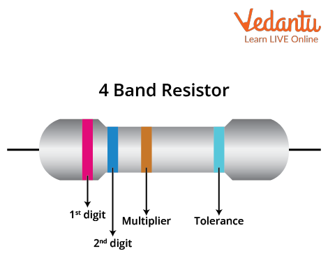
A typical carbon resistor has a cylindrical ceramic body with four or five coloured bands near one end. The bands are positioned closer together on one side, indicating where to begin reading the code from left to right.
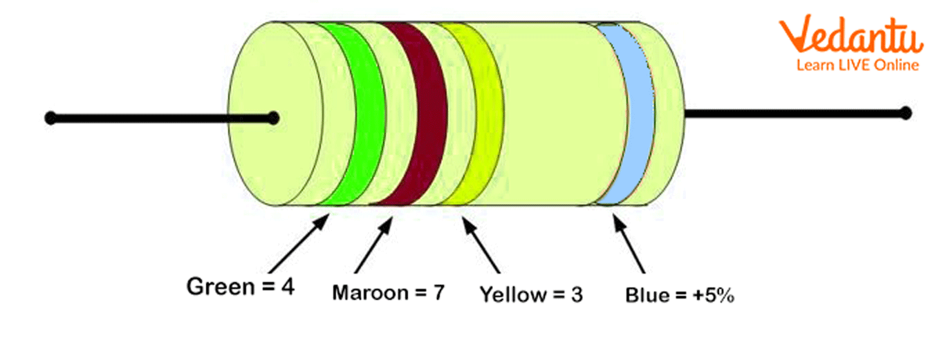
In the most common 4-band resistors, the first two bands represent significant digits, the third band specifies the multiplier, and the fourth band indicates tolerance. For 5-band resistors, the first three bands are significant digits, the fourth is the multiplier, and the fifth denotes tolerance.
Colour Coding Table for Carbon Resistors
Each colour in the coding system corresponds to a specific digit, multiplier, or tolerance value as per the international standard. The table below summarizes these associations for both JEE Main and board exams:
| Colour | Digit / Multiplier / Tolerance |
|---|---|
| Black | 0, ×1 |
| Brown | 1, ×10, ±1% |
| Red | 2, ×100, ±2% |
| Orange | 3, ×1,000 |
| Yellow | 4, ×10,000 |
| Green | 5, ×100,000, ±0.5% |
| Blue | 6, ×1,000,000, ±0.25% |
| Violet | 7, ×10,000,000, ±0.1% |
| Grey | 8, ×100,000,000, ±0.05% |
| White | 9, ×1,000,000,000 |
| Gold | ×0.1, ±5% |
| Silver | ×0.01, ±10% |
| No Band | —, ±20% |
Stepwise Method for Reading Colour Codes
To determine the resistance value, first identify the number of bands and their order (reading from the side with closely spaced bands). Use the colour coding table to decode each band. For four-band resistors, apply the formula: $R = (AB) \times C\,\Omega \pm \text{Tolerance}\%$, where $A$ and $B$ are significant digits, and $C$ is the multiplier.
For example, a resistor with bands Red (2), Violet (7), Yellow (×10,000), and Gold (±5%) has $R = 27 \times 10,000\,\Omega = 270\,\text{k}\Omega \pm 5\%$. In five-band resistors, the formula is $R = (ABC) \times D\,\Omega \pm \text{Tolerance}$, using the three digit bands and one multiplier.
Mnemonic Tricks for Colour Sequence
Remembering the order of colours is essential for quick and error-free decoding. A well-known mnemonic for the digit sequence from Black to White is: “BB ROY of Great Britain Very Good Wife.” This stands for Black, Brown, Red, Orange, Yellow, Green, Blue, Violet, Grey, and White.
It is important to note that Gold and Silver bands do not appear as digit bands. Their roles are limited to the multiplier and tolerance positions in resistor coding. This helps prevent mistakes during the reading process.
Common Mistakes in Decoding Colour Codes
A frequent error is reading the bands from the incorrect end, which can result in a completely wrong resistance value. The tolerance band, usually Gold or Silver, is always kept at the far end or spaced apart to indicate the correct reading direction.
Students sometimes confuse the digit and multiplier bands, or misread the tolerance band as a significant digit. Always refer to the standard table and double-check the sequence before calculation. Practicing with mock tests on topics like Current Electricity Mock Test helps improve accuracy.
Applications in Circuits and Examinations
The colour coding of carbon resistors is widely used in electronics, laboratory work, and exams. It is essential for assembling circuits, verifying resistance values, and troubleshooting. Questions on colour code interpretation are commonly included in JEE Main and board examination patterns.
Accurate identification of resistor values is crucial for solving problems involving Ohm’s law, parallel and series resistor combinations, and error analysis. The colour coding concept is also linked with foundational topics like Coulomb's Law and Electricity and Magnetism in physics.
Summary Tips for Exam Preparation
Students are encouraged to memorize the colour coding chart and practice decoding numerous resistor samples. Downloadable tables or printable revision sheets are recommended for last-minute reference. Mnemonics and consistent practice improve recall speed and accuracy in exams.
Integrating knowledge of resistor colour coding with topics such as Thermal Physics and Laws of Motion enhances understanding of circuit behaviour and practical applications for comprehensive exam success.
To deepen conceptual understanding, students can refer to resources on Electronics, which often integrates colour code analysis with practical circuit design and troubleshooting exercises.


FAQs on Understanding the Colour Coding of Carbon Resistors
1. What is the colour coding of carbon resistors?
Colour coding of carbon resistors is a standardized way to indicate the resistance value using coloured bands.
- Each coloured band represents a specific digit or multiplier.
- The first two or three bands indicate significant digits, the next band is the multiplier, and the last band (if any) is the tolerance.
- For example, the sequence Red-Violet-Yellow-Gold refers to a specific resistance and tolerance value.
2. How do you read the colour bands on a carbon resistor?
To read the colour bands on a carbon resistor, follow these steps:
- Start from the side with the band closest to the edge.
- Identify the first two (or three) bands for significant digits.
- The next band is the multiplier (power of 10).
- The final band, if present, represents tolerance.
3. What is the standard resistor colour code chart?
The standard resistor colour code chart assigns specific digits and multipliers to colours:
- Black: 0
- Brown: 1
- Red: 2
- Orange: 3
- Yellow: 4
- Green: 5
- Blue: 6
- Violet: 7
- Grey: 8
- White: 9
- Gold: multiplier ×0.1, tolerance ±5%
- Silver: multiplier ×0.01, tolerance ±10%
4. How do I calculate the resistance value from the colour code?
To calculate resistance value from the colour code:
- Use the colour chart to assign numbers to the first two bands (significant digits).
- Multiply by the value indicated by the third band (multiplier).
- If a fourth band is present, note it as the tolerance percentage.
5. What is the significance of the tolerance band in carbon resistors?
The tolerance band in carbon resistors indicates the range within which the actual resistance value may vary.
- Gold represents ±5% tolerance.
- Silver shows ±10% tolerance.
- No band usually means ±20% tolerance.
6. Why is colour coding used in resistors instead of direct labeling?
Colour coding is used on resistors because these components are small and direct numbers cannot be printed legibly.
- Enables easy identification without measuring instruments.
- Is standardized internationally for all electrical and electronic professionals.
- Improves accuracy during circuit assembly, as students can quickly check values using the colour code.
7. How many colour bands are present on a typical carbon resistor?
A typical carbon resistor usually has 4 or 5 colour bands.
- 4-band resistors: First two bands (digits), third band (multiplier), fourth band (tolerance).
- 5-band resistors: Three bands (digits), fourth (multiplier), fifth (tolerance).
8. What do the colours red, green, and blue indicate on a resistor?
On a resistor, the colours indicate specific digits as per the resistor colour code:
- Red: 2
- Green: 5
- Blue: 6
9. How to remember the order of resistor colour code easily?
To remember the resistor colour code order, use a mnemonic like:
BBROY Great Britain Very Good Wife—Black, Brown, Red, Orange, Yellow, Green, Blue, Violet, Grey, White.
- Each first letter matches the colour in the sequence.
- This helps students recall values quickly during exams and practicals.
10. What is the use of carbon resistors in electronic circuits?
Carbon resistors are widely used to limit current and divide voltage in circuits.
- They are reliable, low-cost, and offer a range of resistance values.
- Commonly used in school laboratories and practical applications due to their easy identification through colour coding.