


Essential Methods to Solve Series and Parallel Circuits Explained
Circuit solving is a systematic process used to determine currents, voltages, and other electrical quantities in electric circuits. It employs physical laws, such as Ohm’s Law and Kirchhoff’s Laws, to derive mathematical relationships for analyzing circuit behavior under various configurations.
Classification of Electric Circuits
Electric circuits are classified based on their structure and the type of elements they contain. Common types include open circuits, closed circuits, DC circuits, AC circuits, series circuits, parallel circuits, and series-parallel circuits.
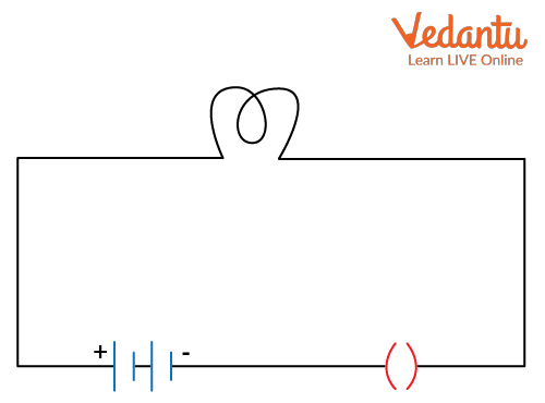
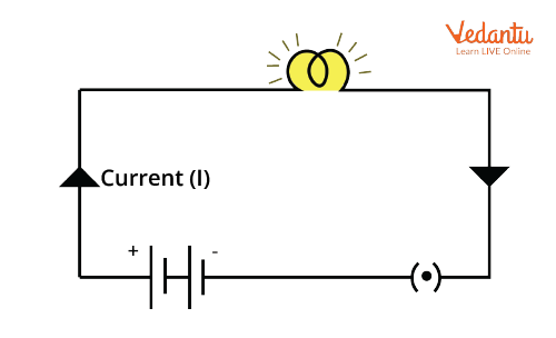
An open circuit is one where the electrical path is incomplete, resulting in zero current through the circuit. In contrast, a closed circuit has a complete conducting path, allowing current to flow from the power source through each component.
DC circuits utilize sources providing a constant voltage or current, causing unidirectional current flow. AC circuits employ alternating sources, where current and voltage periodically vary in magnitude and direction.
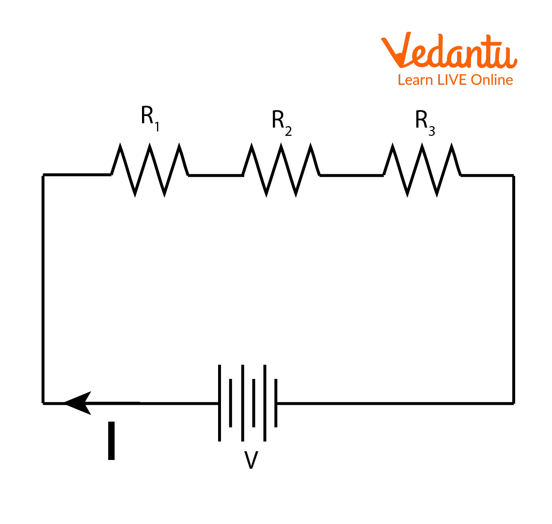
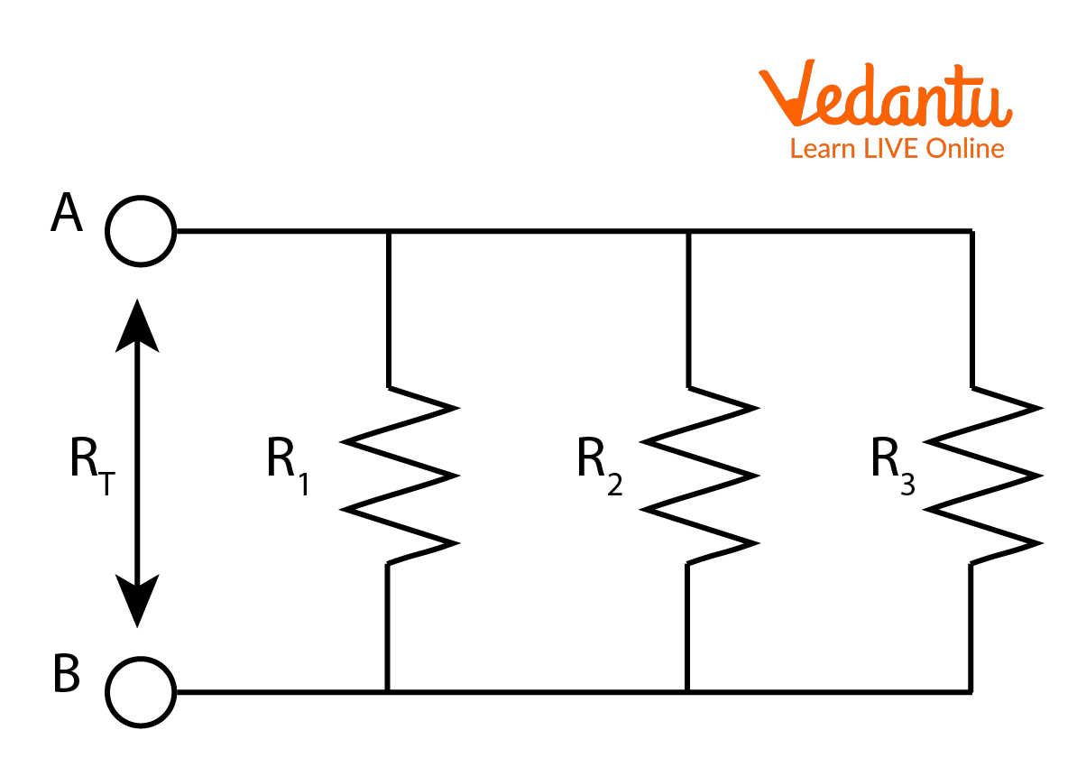
In a series circuit, resistive components are connected sequentially so that the same current flows through each resistor. In a parallel circuit, resistors are connected across common nodes, leading to the same voltage across each branch.
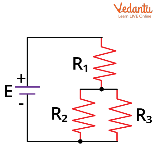
Series-parallel circuits consist of some resistors connected in series and others in parallel. Such configurations require careful analysis to determine the overall circuit behavior.
Fundamental Laws Used in Circuit Solving
Two primary laws are essential for analyzing and solving linear circuits: Ohm’s Law and Kirchhoff’s Laws, which relate voltages, currents, and resistances in circuit elements. These form the foundation of circuit analysis at JEE level.
Ohm's Law states the linear relationship between voltage, current, and resistance in a conductor. It is mathematically expressed as $V = IR$, where $V$ is the potential difference, $I$ is the current, and $R$ is the resistance of the element.
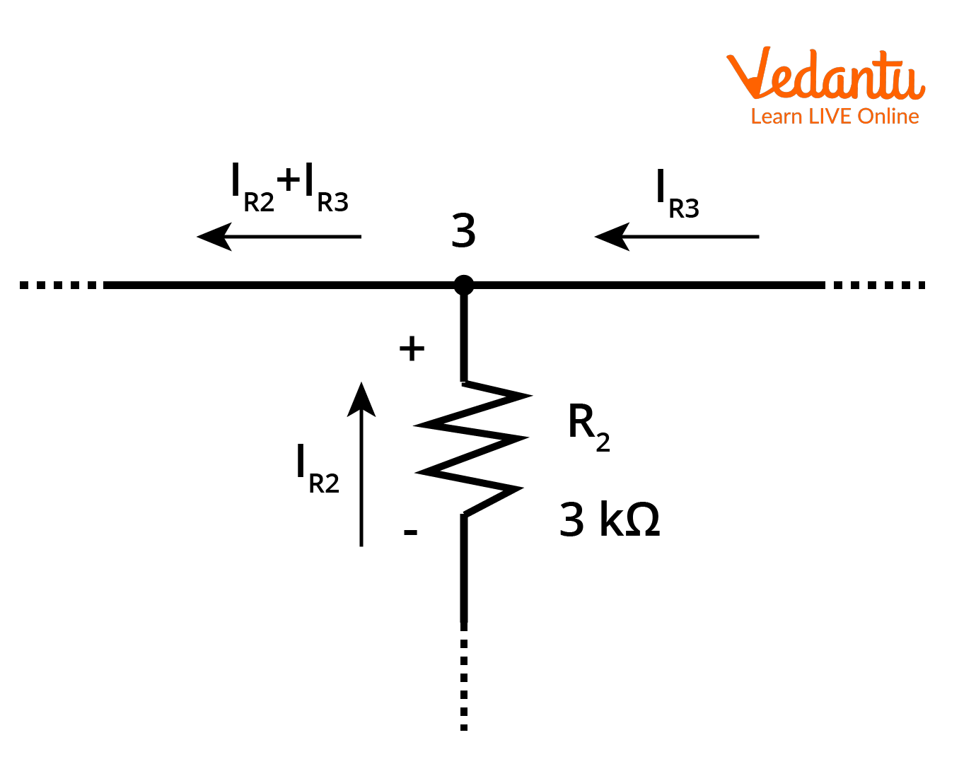
Kirchhoff’s Current Law (KCL) states that at any junction, the algebraic sum of currents entering and leaving is zero. This ensures conservation of charge within the circuit network.
Kirchhoff’s Voltage Law (KVL) states that in any closed loop, the algebraic sum of all potential differences equals zero. This law maintains the conservation of energy in electrical circuits.
Component Constituent Equations
The behavior of each circuit element is described by its own voltage-current relationship, known as the constituent equation. For resistors, the equation is $V=IR$. For ideal voltage sources, the voltage difference is maintained constant. For ideal current sources, the current is fixed regardless of voltage.
| Component | Constituent Equation |
|---|---|
| Resistor | $V = IR$ |
| Ideal Voltage Source | $V = \text{constant}$ |
| Ideal Current Source | $I = \text{constant}$ |
Each component in a circuit provides one mathematical equation connecting its voltage and current. These equations are combined with KCL and KVL to form a complete solvable system.
Circuit Analysis Methods
Several systematic methods are used for circuit solving, including series-parallel reduction, Ohm’s Law, Kirchhoff’s Laws, nodal analysis, mesh analysis, and the superposition theorem. The choice of method depends on the circuit’s complexity.
- Series and parallel reductions for simple circuits
- Kirchhoff’s Laws for complex networks
- Superposition for linear circuits with multiple sources
When circuits contain both series and parallel elements, reduction techniques are used iteratively. For circuits with multiple loops or nodes, algebraic equation systems derived using KVL and KCL are solved, often by matrix methods.
The superposition theorem is applied to circuits containing multiple independent sources, allowing calculation of current or voltage responses by considering one source at a time and summing the results. More details can be found in Kirchhoff's Laws of Electric Circuits.
Stepwise Approach for Solving Linear DC Circuits
Solving a linear DC circuit systematically involves defining variables, applying fundamental laws, and deriving equations. The steps are as follows:
- Identify and label all circuit nodes
- Assign current directions in each branch
- Apply KCL at each non-reference node
- Apply KVL around each independent loop
- Write constituent equations for each element
- Solve the resulting algebraic system for unknowns
For circuits with only resistors and independent sources, the system of equations is linear and can be solved using substitution, elimination, or matrix methods. Such processes are similar in concept to the methods discussed in Difference Between Series And Parallel Circuits.
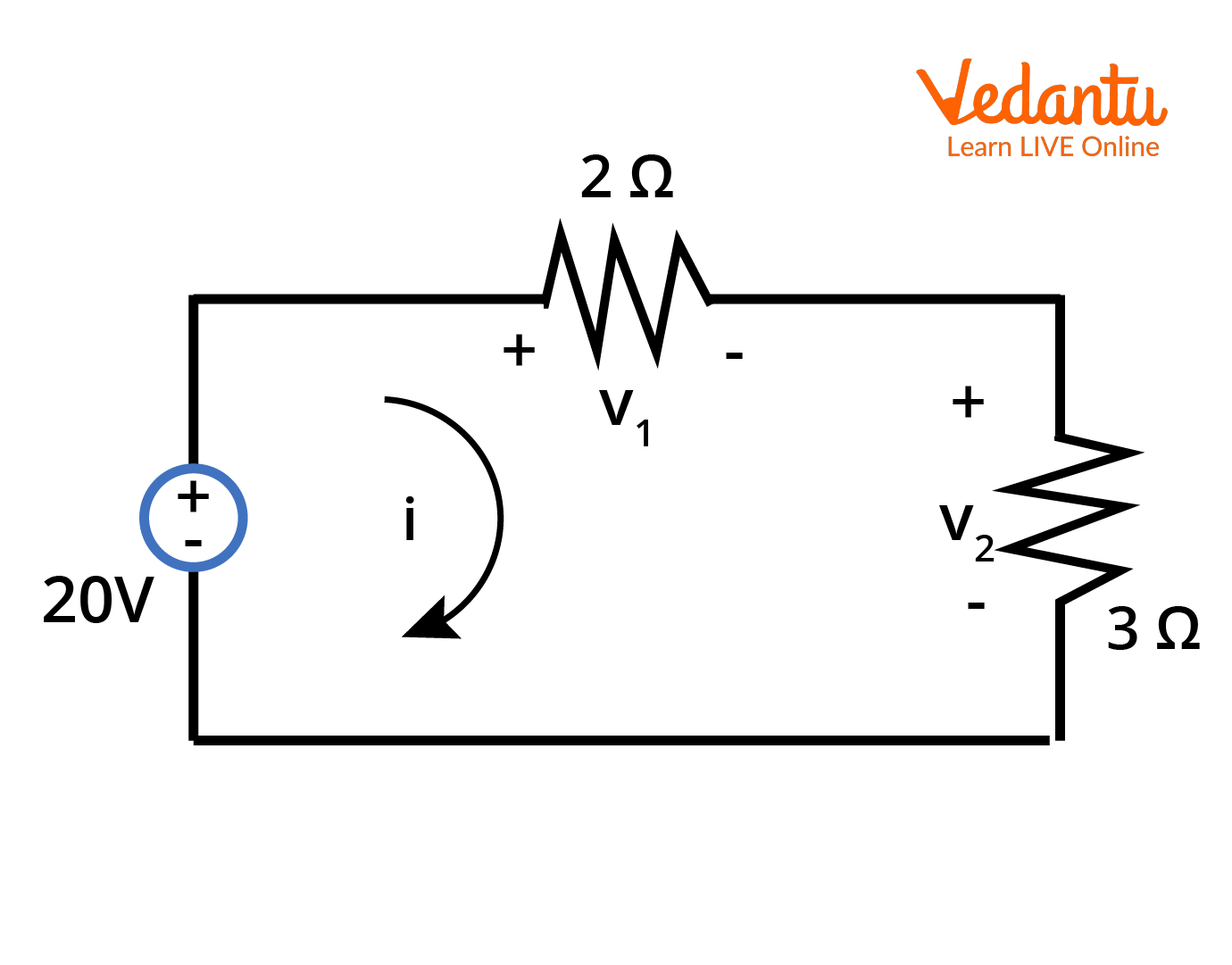
Illustrative Example: Series Circuit Analysis
Consider a series circuit with a voltage source $V$ and two resistors $R_1$ and $R_2$ connected in series. The total resistance is $R_{eq} = R_1 + R_2$. The current in the circuit is $I = \dfrac{V}{R_{eq}}$.
The potential drop across $R_1$ is $V_1 = I R_1$, and across $R_2$ is $V_2 = I R_2$. The sum of these potential drops equals the source voltage, as stated by KVL.
Illustrative Example: Parallel Circuit Analysis
In a parallel circuit, the equivalent resistance is found using $\dfrac{1}{R_{eq}} = \dfrac{1}{R_1} + \dfrac{1}{R_2} + \ldots + \dfrac{1}{R_n}$. The current from the source splits among the parallel branches, and each branch has the same voltage across it.
If the total current is $I$, then the current in branch $k$ is $I_k = \dfrac{V}{R_k}$. The sum of branch currents gives the total current.
Application to Complex Circuits
For circuits containing mixed series and parallel resistances, or multiple power sources, methods such as nodal analysis and mesh analysis are used. This involves writing a separate equation for each independent node or loop and solving the system using algebraic techniques.
Modified nodal analysis and matrix formulations are efficient for larger systems, especially when using computational methods. Explanation on analogous methods can be found in Circuit Solving.
Power in Circuit Elements
Power consumed or supplied in circuit elements is calculated using the expressions $P = VI$, $P = I^2R$, or $P = \dfrac{V^2}{R}$, depending on the known variables. For resistors, power is always dissipated as heat.
Key Points for Effective Circuit Solving in JEE
- Systematically label nodes and assign current directions
- Apply fundamental laws rather than memorizing results
- Check results for consistency with physical laws
- Be attentive to sign conventions and passive sign convention
- Break complex systems into manageable parts
Understanding circuit solving by using the above methods enhances problem-solving ability in both theory and numerical problems found in JEE Main Physics. For analysis involving capacitive and inductive elements, see also problems related to RC Circuit.
Accurate analysis of electrical circuits relies on a systematic application of basic laws and the correct use of reduction and algebraic techniques. This approach is fundamental to topics such as the Difference Between Ammeter And Galvanometer and the Difference Between Current And Voltage.
FAQs on How to Solve Electrical Circuits: A Student’s Guide
1. What is circuit solving in physics?
Circuit solving refers to the process of analyzing electrical circuits to find unknown values like current, voltage, and resistance. It involves using standard principles such as Ohm's Law and Kirchhoff's Laws to determine the behavior of complex circuits.
- Apply Ohm’s Law (V = IR).
- Use series and parallel circuit rules.
- Implement Kirchhoff’s Voltage Law (KVL) and Kirchhoff’s Current Law (KCL).
- Break complex circuits into smaller, manageable parts.
2. How do you solve a simple series circuit?
To solve a series circuit, add up all resistances and use Ohm’s Law to find current and voltage:
- Total resistance (Rtotal) = R1 + R2 + ...
- Current is the same through every component.
- Use V = IR to find current or voltage as required.
- Voltage across each resistor: Vx = I × Rx.
3. What are the basic rules for solving parallel circuits?
To solve a parallel circuit, understand that the voltage is same across all branches, and current divides among them:
- Total resistance (Rtotal) = 1/(1/R1 + 1/R2 + ...)
- Each resistor has the same voltage.
- Current in each branch: Ix = V / Rx.
- Total current is the sum of branch currents.
4. What is Ohm’s Law and how is it used in circuit solving?
Ohm’s Law states that the current passing through a conductor is directly proportional to the voltage and inversely proportional to the resistance. It is given by V = IR.
- V: Voltage (in volts)
- I: Current (in amperes)
- R: Resistance (in ohms)
5. How can I apply Kirchhoff’s laws to solve a circuit?
Kirchhoff’s Laws are used to analyze more complex circuits containing multiple loops or junctions.
- Kirchhoff’s Current Law (KCL): The total current entering a junction equals the total current leaving.
- Kirchhoff’s Voltage Law (KVL): The sum of all voltages around a closed loop is zero.
- Write equations based on these laws and solve for the unknowns.
6. What is the difference between series and parallel circuits in terms of circuit solving?
In series circuits, resistances add directly and current is the same everywhere. In parallel circuits, total resistance decreases and current splits across branches.
- Series: Current is constant, voltage divides.
- Parallel: Voltage is constant, current divides.
7. What are the steps to solve a complex circuit problem?
To solve a complex electrical circuit, follow a systematic method:
- Identify all known and unknown values.
- Simplify the circuit if possible (combine resistors).
- Apply Ohm’s Law, KCL, and KVL.
- Set up simultaneous equations for unknowns.
- Solve step by step, checking units and directions.
8. Can you explain with an example how to solve a circuit using Ohm’s Law?
Certainly. If a series circuit has 12V battery and two resistors (2Ω and 4Ω):
- Total resistance: 2 + 4 = 6Ω.
- Current: I = V/R = 12V / 6Ω = 2A.
- Voltage across 2Ω: 2A × 2 = 4V.
- Voltage across 4Ω: 2A × 4 = 8V.
9. How do you identify if resistors are in series or parallel when solving circuits?
Resistors are in series if they are connected end-to-end, sharing only a single path for current. They are in parallel if they are connected to the same two points, having multiple current paths.
- Trace the path of current through the circuit diagram.
- Check if same current flows: series.
- Check if same voltage: parallel.
10. Why is circuit solving important in physics and engineering?
Circuit solving is crucial in physics and engineering because it helps understand, design, and troubleshoot electrical systems.
- Enables designing safe and effective circuits.
- Assists in diagnosing faults and optimizing performance.
- Essential for fields like electronics, electrical engineering, and physics exams.