


Rules and Examples of Sign Convention in Ray Diagrams
Sign convention in optics helps us assign positive and negative values to distances and heights in ray diagrams and numerical problems. This systematic approach reduces errors in image location, magnification, and focal length calculations for both mirrors and lenses.
Understanding the Sign Convention in Ray and Geometrical Optics
In ray optics, the Cartesian sign convention is a universal rule for assigning signs. The origin is set at the mirror’s pole or the lens’s optical center, and the principal axis is taken as the horizontal x-axis. All measurements follow this axis.
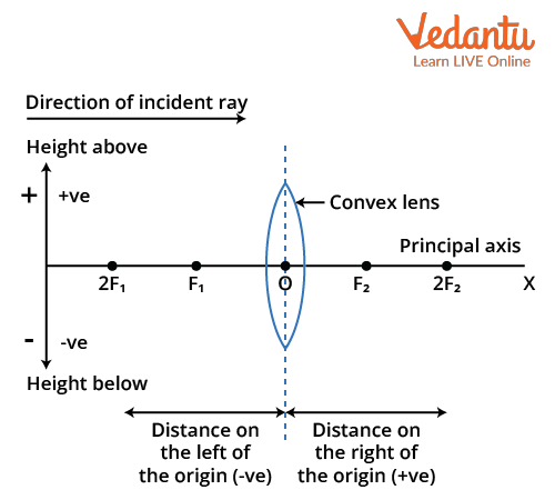
Distances measured in the direction of incident light are positive. Distances measured against the direction of incident light are negative. This core rule underpins most problems in geometrical optics for JEE and beyond.
Heights above the principal axis are always positive, while those below are negative. This helps determine if images are real or virtual, as well as their orientation.
Real-World Intuition: Visualizing the Cartesian Sign Convention
Imagine standing at a road’s origin point, with cars heading to your right as positive and to your left as negative. This mental model mimics how distances are assigned in optics using the Cartesian sign convention.
It becomes effortless to remember signs when you think of light traveling left to right, and everything measured from the reference point—either a pole or optical center—along or against the light’s movement.
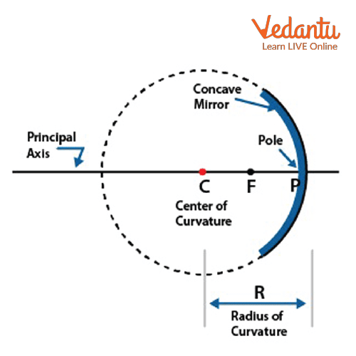
How Signs Work for Spherical Mirrors
For spherical mirrors, incident rays in most problems come from the left. The pole acts as the origin. Object distance (u) is generally negative because it’s to the left of the pole, against the light.
Image distance (v) can be positive or negative. If the image is formed on the side where reflected rays go, it follows the light direction and is positive. Otherwise, it is negative.
The focal length (f) for concave mirrors is negative (focus lies to the left), and for convex mirrors, it is positive (focus lies to the right).
Sign Convention Rules for Lenses
For lenses, the optical center is the origin. Object distance (u) is usually negative, as real objects are placed to the left, against incident light. This keeps the sign consistent with mirrors.
A convex lens has a positive focal length, because its focus is to the right, following the light. For a concave lens, the focal length is negative, as the focus is to the left.
Comparison Table: Sign Convention in Mirrors vs. Lenses
| Parameter | Sign Rule |
|---|---|
| Origin | Pole (mirror), Optical Center (lens) |
| Object Distance (u) | Negative (usually left) |
| Image Distance (v) | Positive or Negative |
| Focal Length (f) | Concave/Concave lens: Negative |
| Focal Length (f) | Convex/Convex lens: Positive |
| Height above axis | Positive |
| Height below axis | Negative |
Key Equations Using Sign Convention
In lens and mirror problems, always apply the sign convention before calculation. This keeps the mathematics in ray optics consistent and reliable for JEE-level physics.
For mirrors, use the formula:
$ \dfrac{1}{f} = \dfrac{1}{v} + \dfrac{1}{u} $
For lenses, the formula is:
$ \dfrac{1}{f} = \dfrac{1}{v} - \dfrac{1}{u} $
Magnification is calculated by:
$ m = \dfrac{h'}{h} = \dfrac{v}{u} $
You can reinforce your understanding with topics like Difference Between Mirror And Lens for clarity on device-specific conventions.
Numerical Example: Image Formation by a Concave Lens
A real object is placed 30 cm to the left of a concave lens with a focal length of 20 cm.
Given: $u = -30$ cm, $f = -20$ cm
Formula: $ \dfrac{1}{f} = \dfrac{1}{v} - \dfrac{1}{u} $
Substitute the values: $ \dfrac{1}{-20} = \dfrac{1}{v} - \dfrac{1}{-30} $
$ \dfrac{1}{v} = \dfrac{1}{-20} + \dfrac{1}{30} $
$ \dfrac{1}{v} = -\dfrac{1}{20} + \dfrac{1}{30} = -\dfrac{3}{60} + \dfrac{2}{60} = -\dfrac{1}{60} $
So $v = -60$ cm. The negative sign shows the image is virtual and forms to the left of the lens, on the same side as the object.
Practice Question for Deeper Understanding
A convex mirror has a focal length of 15 cm. If an object is placed 25 cm in front of it, where will the image form? Apply the sign convention in your calculation for full marks.
Applications of Sign Convention in Daily Life and Technology
Drivers rely on the correct sign convention with convex mirrors, as it helps to form virtual images for rearview safety. Similar sign use is essential in lens-based camera focusing and in spectacle design in Sign Convention Of Lens And Mirror.
Engineers use sign conventions for lens alignment in optical instruments, from microscopes to projectors. Proper sign use guarantees precise imaging and system performance.
Common Mistakes to Avoid When Applying Sign Convention
Students often mix up the sign of focal length for concave and convex optics. Always check the side of focus relative to the origin before assigning the sign, to avoid errors seen in Difference Between Real Image And Virtual Image.
Another error is measuring all distances from the wrong point. Use the pole for mirrors and optical center for lenses every time. This ensures the signs stay true to the sign convention in ray optics class 12.
Comparison Table: Cartesian vs. Non-Cartesian Sign Convention
| Aspect | Cartesian Convention |
|---|---|
| Axis | Principal axis as x-axis |
| Origin Point | Pole or optical center |
| Positive Direction | Along incident ray |
| Negative Direction | Opposite to incident ray |
| Heights | Above axis: positive, below: negative |
Linking Sign Convention with Key Physics Concepts
The sign convention in ray optics is tightly integrated with other optics concepts. It is critical to apply these sign rules when learning about Mirror Formula And Magnification to keep calculations accurate.
Sign assignment also plays a role in advanced studies of refraction and lens combinations. You can explore more detailed scenarios in Refraction Of Light Through A Glass Slab.
Key Characteristics of the Sign Convention in Visual and Geometric Optics
- Measurements are always from the designated reference point
- All sign rules flow from the direction of incident light
- Consistency is vital for reliable numerical solutions
- Helps avoid misinterpretation of image nature and position
- Basis for problem-solving in competitive exams like JEE
Spherical mirrors have specific applications in vehicles and optical instruments where precise image location is vital. Read more in Uses Of Spherical Mirrors.
Related Topics in Physics
Ray diagrams, Refraction and reflection, Lens maker’s formula, Spherical aberration, Power of a lens, Prism formula, Total internal reflection, Electromagnetic waves, Dispersion of light, Optical fiber applications, Telescopes and microscopes.