


Revision Notes on Alternating Current for NEET 2026 - Free PDF Download
Direct current is the current that may or may not change in magnitude but does not change in its direction.
Alternating current is the current which changes continuously in magnitude and direction periodically. It can be represented by a sine curve or a cosine curve
$I = {I_0}\sin \omega t$ Or $I = {I_0}\cos \omega t$
Here, ${I_0}$ is peak value of current and is known as amplitude of ac, $I$ is instantaneous value of alternating current.
$\omega = 2\pi T$ $= 2\pi \upsilon$ where T is the period of ac and ν is frequency.
Mean or average value of alternating current or volts over one complete cycle:
The mean or average value of alternating current voltage over one complete cycle is zero.
$I_{av}$ or $\bar{I}$ or $I_{av}=\dfrac{\int_{0}^{T} I_{0} \sin \omega d t}{\int_{0}^{T} d t}=0, V_{m}$ or $\bar{V}$ or $V_{a n}=\dfrac{\int_{0}^{T} V_{0} \sin \omega d t}{\int_{0}^{T} d t}=0$
Average value of alternating current for first half equation is:
$I_{a v>}=\dfrac{\int_{0}^{T / 2} I_{0} \sin \omega d t}{\int_{0}^{T / 2} d t}=\dfrac{2 I_{0}}{\pi}=0.637 I_{0}$
Similarly, for alternating voltage, the average value of first half cycle is
$V_{a v}=\dfrac{\int_{0}^{T / 2} V_{0} \sin \omega d t}{\int_{0}^{T / 2} d t}=\dfrac{2 V_{0}}{\pi}=0.637 V_{0}$
Average value of alternating current for second cycle is
$I_{a v^{\prime}}=\dfrac{\int_{T / 2}^{T} I_{0} \sin \omega d t}{\int_{T / 2}^{T} d t}=-\dfrac{2 I_{0}}{\pi}=-0.637 I_{0}$
Root Mean Square (rms) Value of Alternating Current:
It is defined as that value of steady current, which would generate the same amount of heat in a given resistance in a given time, as is done by the alternating current when passed through the same resistance for the same time. The RMS value of alternating current is also known as the effective value or virtual value of ac. It is represented by
${I_{rms}}$ ,${I_{eff}}$ or ${I_v}$ .
${I_{rms}}$ or ${I_v} = \dfrac{{{I_0}}}{{\sqrt 2 }} = 0.707{I_0}$
Similarly, for alternating voltage:
${V_{rms}}$ OR ${V_{rms}} = \dfrac{{{V_0}}}{{\sqrt 2 }} = 0.707{V_0}$
Form Factors:
Form factor is ratio of rms value to average value of alternating current or voltage during half cycle. Form factor = $\dfrac{{{I_{rms}}}}{{{I_{av}}}} = \dfrac{{\dfrac{{{I_o}}}{{\sqrt 2 }}}}{{\dfrac{{2{I_o}}}{\pi }}} = \dfrac{\pi }{{2\sqrt 2 }} = 1.11$
AC Circuit Containing Pure Resistance only:
AC circuit with pure resistor
Let $V = {V_0}\sin \omega t$
Then, $I = \dfrac{V}{R} = \dfrac{{{V_0}}}{R}\sin \omega t = {I_0}\sin \omega t$
Here the alternating voltage is in phase with current, when ac flows through a resistor.
Phasor Graph of a Resistive Circuit
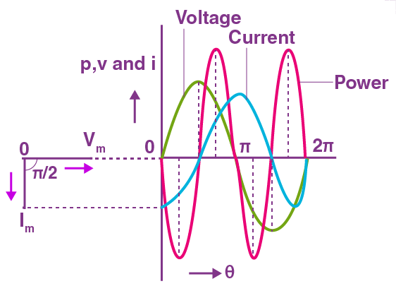
AC Circuit Containing Pure Inductor only:
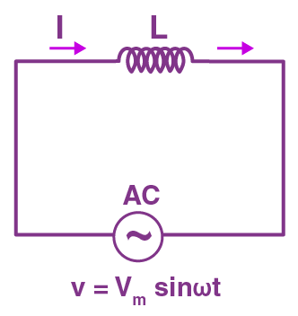
AC Circuit with pure Inductor
Let $V = {V_0}\sin \omega t$
Then, $I = {I_0}\sin \left( {\omega t - \dfrac{\pi }{2}} \right)$
Where ${I_0} = \dfrac{{{V_0}}}{{\omega L}}$
Thus, the alternating current lags behind the alternating voltage by a phase angle of $\dfrac{\pi }{2}$ when ac flows through an inductor.
Inductive reactance: It is the opposition offered by the inductor to the flow of alternating current through it.
${X_L} = \omega L = 2\pi \upsilon L$
The inductive reactance is zero for dc $\left( {\upsilon = 0} \right)$ and has a finite value for ac.
Phasor Graph for a Inductive Circuit
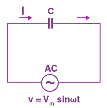
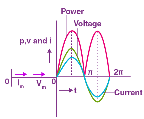
AC Circuit Containing Pure Capacitor only:
AC Circuit with Pure Capacitor
Let $V = {V_0}\sin \omega t$
$I = {I_0}\sin \left( {\omega t + \dfrac{\pi }{2}} \right)$
Where ${I_0} = (\omega C){V_0}$ .
Thus, the alternating current leads the voltage by a phase angle of $\dfrac{\pi }{2}$ , when ac flows through a capacitor.
Capacitive reactance: It is the opposition offered by the capacitor to the flow of alternating current through it. The capacitive reactance is infinite for dc $\left( {\upsilon = 0} \right)$ and has a finite value for ac.
${X_C} = \dfrac{1}{{\omega C}} = \dfrac{1}{{2\pi \upsilon C}}$
The capacitance reactance is infinite for dc $\left( {\upsilon = 0} \right)$ and has a finite value for ac.
Phasor graph of a capacitive circuit
AC circuit with an inductor and a resistor:
A circuit with an inductor and a resistor is called an LR circuit in series. Here, $Z = \sqrt {{R^2} + X_L^2}$ is the impedance of the circuit.

LR Circuit with Phasor Diagram
As in the figure the current lags the voltage by an angle $\phi = {\tan ^{ - 1}}\left( {\dfrac{{{X_L}}}{R}} \right)$ .
AC circuit with an inductor and a capacitor:
A circuit which has an inductor and capacitor connected in series is called an LC circuit. Oscillations produced by it are called LC oscillations.
Here, $Z = {X_c} - {X_L}$ is the impedance and the current leads voltage by an angle 90.

Phasor Diagram of an LC Circuit
In LC oscillations charge q, I and $\dfrac{{dI}}{{dt}}$ all oscillate with the same angular frequency. But the phase difference is always 90.
Thus we have AC: $I = - {q_o}\omega \sin \omega t$ .
AC circuit with a resistor and a capacitor:
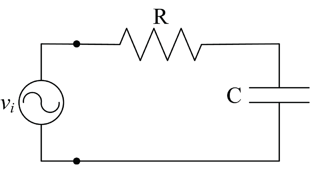
RC Circuit
A circuit with a resistor and a capacitor connected in series is called a RC circuit. Here, $Z = \sqrt {{R^2} + X_c^2}$ is the impedance and the current leads voltage by an angle $\phi = {\tan ^{ - 1}}\left( {\dfrac{{{X_c}}}{R}} \right)$ .
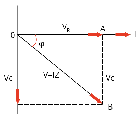
Phasor Diagram of a RC Circuit
Series LCR circuit:
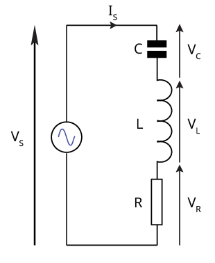
Series LCR Circuit
Let $V = {V_0}\sin \omega t$
Then, $I = {I_0}\sin (\omega t - \phi )$
Where ${I_0} = \dfrac{{{V_0}}}{Z}$
Here Z is the impedance of the series LCR circuit.
$Z = \sqrt {{R^2} + {{({X_L} - {X_C})}^2}} = \sqrt {{R^2} + {{\left( {\omega L - \dfrac{1}{{\omega C}}} \right)}^2}}$
The alternating current lags behind the voltage by a phase angle ϕ
$\tan \phi = \dfrac{{{X_L} - {X_C}}}{R}$
When ${X_L} > {X_C}$ , tan ϕ is positive. Therefore, ϕ is positive. Hence current lags behind the voltage by a phase angle ϕ. The ac circuit is an inductance dominated circuit.
When ${X_L} > {X_C}$ , tan ϕ is negative. Therefore, ϕ is negative. Hence current leads the voltage by a phase angle ϕ. The ac circuit is a capacitance dominated circuit.
Impedance triangle:
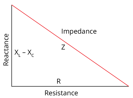
Impedance Triangle of a LCR Circuit
It is a right angled triangle, whose base represents ohmic resistance (R), perpendicular represents reactance $({X_L} - {X_C})$ and hypotenuse represents impedance (Z) of the series LCR circuit as shown in figure above.
Impedance of circuit
$Z = \sqrt {{R^2} + {{({X_L} - {X_C})}^2}}$
Admittance:
The reciprocal of the impedance of an ac circuit is known as admittance. It is represented by Y.
$\therefore$ Admittance = $\dfrac{1}{\text{Impedance}}$ or $Y = \dfrac{1}{Z}$
The unit of admittance is $(ohm){}^{ - 1}$ or Siemens.
Susceptance:
The reciprocal of the reactance of an ac circuit is known as susceptance. It is represented by S.
$\therefore$ Susceptance = $\dfrac{1}{\text{Reactance}}$
The unit of susceptance is $(ohm){}^{ - 1}$ or Siemens.
Inductive susceptance = $\dfrac{1}{\text{Inductive Reactance}}$
Or ${S_L} = \dfrac{1}{{{X_L}}} = \dfrac{1}{{\omega L}}$
Capacitive susceptance = $\dfrac{1}{{Capacitive\operatorname{Re} ac\tan ce}}$
Or ${S_C} = \dfrac{1}{{{X_C}}} = \dfrac{1}{{\dfrac{1}{{\omega C}}}} = \omega C$
Resonant series LCR circuit:
When the frequency of AC supply is such that the inductive reactance and capacitive reactance are equal $\left(X_{L}=X_{C}\right)$.
The impedance of the series LCR which is equal to the ohmic resistance in the circuit. As the current in the circuit becomes maximum. Such series LCR circuit is known as resonant series of circuit and the frequency of the AC supply is known resonant frequency $({\upsilon _r})$ . The resonant frequency is
${\upsilon _r} = \dfrac{1}{{2\pi \sqrt {LC} }}$
${\omega _r} = \dfrac{1}{{\sqrt {LC} }}$
The series resonance circuit is known as acceptance circuit. It is used in radio and TV receiver’s sets of tuning a particular radio station/TV channel.
A circuit exhibits the resonance phenomenon if both L and C are present in the circuit. Then the voltage across L and C cancels each other. We can have resonance in an LR or RC circuit.
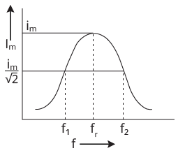
Condition of resonance in a series LCR circuit with a graph
Parallel LCR circuit:
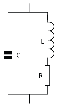
Parallel LCR circuit
Similar to a series LCR circuit, parallel LCR circuit has:
$\dfrac{1}{Z} = \sqrt {{{\left( {\dfrac{1}{R}} \right)}^2} + {{\left( {\dfrac{1}{{{X_L}}} - \dfrac{1}{{{X_C}}}} \right)}^2}}$
${f_r} = \dfrac{1}{{2\pi }}\sqrt {\dfrac{1}{{LC}} - \dfrac{{{R^2}}}{{{L^2}}}} ,{Z_r} = \dfrac{L}{RC}$
Other quantities such as admittance, and susceptance remain the same.
Quality factor:
It is a measure of the sharpness of the resonance. It is defined as the ratio of the reactance of either the inductance or capacitance at the resonant angular frequency to the total resistance of the circuit.
$Q = \dfrac{{{X_L}}}{R} = \dfrac{{{\omega _r}L}}{R}$
$Q = \dfrac{{{X_c}}}{R} = \dfrac{1}{{{\omega _r}CR}}$
$\therefore Q = \dfrac{1}{R}\sqrt {\dfrac{L}{C}}$
Quality factor is also expressed in terms of bandwidth
$Q = \dfrac{\text{Resonant frequency}}{\text{Bandwidth}}$
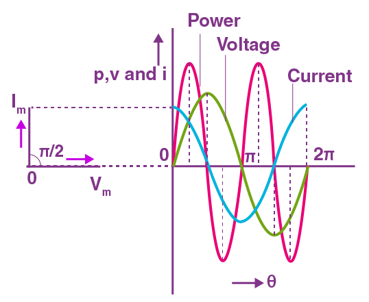
Power in an AC circuit:
In an ac circuit we may define three types of power.
Instantaneous power: The power in the AC circuit at any instant of time is known as instantaneous power. it is equal to the product of values of alternating voltage and alternating current at that time.
Average power (${P_{av}}$ ): The power average over one full cycle of AC is known as average power. It is also known as true power.
${P_{av}} = {V_{rms}}{I_{rms}}\cos \phi = \dfrac{{{V_0}{I_0}}}{2}\cos \phi$
Apparent power: The product of virtual voltage (${V_{rms}}$ ) and virtual current (${I_{rms}}$ ) in the circuit is known as virtual power.
${P_v} = {V_{rms}}{I_{rms}} = \dfrac{{{V_0}{I_0}}}{2}$
Power factor:
It is defined as the ratio of true power to apparent power of an AC circuit
$\cos \phi = \dfrac{\text{True power}}{\text{Apparent power}}$
Power factor is also defined as the ratio of the resistance to the impedance of an ac circuit
$\cos \phi = \dfrac{R}{Z}$
It is unit-less and dimensionless.
In pure resistive circuit,
$\phi = {0^0}$ ;$\cos \phi = 1$
In pure inductive or capacitive circuit
$\phi = \dfrac{\pi }{2}$ ;$\cos \phi = 0$
In RL circuit,
$Z = \sqrt {{R^2} + {X_L}^2}$ and $\cos \phi = \dfrac{R}{Z}$
In RC circuit,
$Z = \sqrt {{R^2} + {X_C}^2}$ and $\cos \phi = \dfrac{R}{Z}$
In series LCR circuit,
$Z = \sqrt {{R^2} + {{({X_L} - {X_C})}^2}}$ and $\cos \phi = \dfrac{R}{Z}$
At resonance, ${X_L} = {X_C}$
$\therefore Z = R$ and $\phi = {0^0}$
Watt less current:
The average power associated over a complete cycle with a pure inductor or pure capacitor is zero, even though a current is flowing through them. This current is known as the watt less current or idle current.
Transformer:
It is a device used for converting a low alternating voltage to a high alternating voltage and vice versa. It is based on the principle of mutual induction.
There are two types of transformer: Step-up and Step-down transformers.
For ideal transformer, $\dfrac{{{V_s}}}{{{V_p}}} = \dfrac{{{I_p}}}{{{I_s}}} = \dfrac{{{N_s}}}{{{N_p}}} = k$ f
Where k is called the transformation ratio.
For a step-up transformer, k > 1. i.e. ${V_s} > {V_p}$ , ${I_s} > {I_p}$ and ${N_s} > {N_p}$ .
For a step-down transformer, k < 1. I.e. ${V_s} < {V_p}$ , ${I_s} < {I_p}$ and ${N_s} < {N_p}$ .
Power losses in a transformer are: Copper loss, Iron loss, Loss due to flux leakage, Hysteresis etc…
Efficiency of a transformer,
$\eta = \dfrac{\text{output power}}{\text{input power}} = \dfrac{{{V_s}{I_s}}}{{{V_p}{I_p}}}$
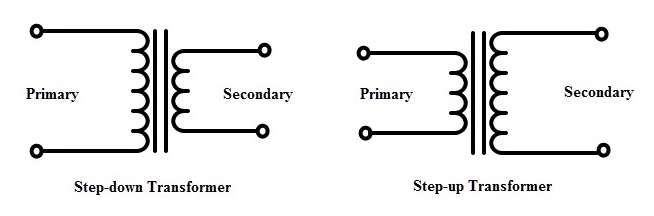
Types of transformers
AC generator/dynamo:
An AC generator/Dynamo produces alternating current energy from mechanical energy of rotation of a coil. It is based on the phenomenon of electromagnetic induction. The form of EMF induced is $\varepsilon = {\varepsilon _o}\sin \omega t$ , where ${\varepsilon _0} = NAB\omega$ , max.emf induced. Here, N is total number of turns in the coil, A is face of the coil, B is strength of magnetic field applied and w is angular velocity of the armature coil.
DC Generator:
A DC generator/Dynamo produces direct current from mechanical energy of rotation of a coil. Its primary and working are the same as those of AC generators. There is only a little change in the design of the generator slip ring arrangement used in AC generators is replaced by split ring arrangement in DC generators.
DC motor:
A DC motor converts direct current energy from a battery into mechanical energy of rotation. It is based on the fact that when a coil carrying current is placed in a magnetic field, it experiences a torque which may cause the coil. The efficiency of a DC motor is given by: $\eta=\frac{\text { back emf }}{\text { emf of battery }}$
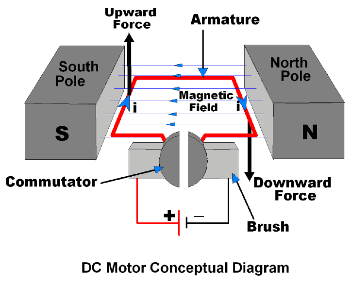
DC Motor
Points to remember:
Alternating current is the current which changes continuously in magnitude and in direction periodically. It can be represented by a sine curve or a cosine curve
$I = {I_0}\sin \omega t$ Or $I = {I_0}\cos \omega t$
The mean or average value of alternating current voltage over one complete cycle is zero.
${I_{av}}$ or $\bar I$ or ${I_{av}} = \dfrac{{\int\limits_0^T {{I_0}\sin \omega dt} }}{{\int\limits_0^T {dt} }} = 0$ , ${V_m}$ or $\bar V$ or ${V_{av}} = \dfrac{{\int\limits_0^T {{V_0}\sin \omega dt} }}{{\int\limits_0^T {dt} }} = 0$
Root mean square of alternating current is defined as that value of steady current, which would generate the same amount of heat in a given resistance in a given time, as is done by the alternating current when passed through the same resistance for the same time.
The RMS value of alternating current is also known as effective value or virtual value of ac. It is represented by${I_{rms}}$ ,${I_{eff}}$ or${I_v}$ .
${I_{rms}}$ or ${I_v} = \dfrac{{{I_0}}}{{\sqrt 2 }} = 0.707{I_0}$
Form factor is ratio of rms value to average value of alternating current or voltage during half cycle. Form factor = $\dfrac{{{I_{rms}}}}{{{I_{av}}}} = \dfrac{{\dfrac{{{I_o}}}{{\sqrt 2 }}}}{{\dfrac{{2{I_o}}}{\pi }}} = \dfrac{\pi }{{2\sqrt 2 }} = 1.11$
The alternating voltage is in phase with current when ac flows through a resistor but lags the voltage by a phase angle of 90 for an inductive circuit and leads the voltage by an phase angle of 90 for a capacitive circuit.
Let $V = {V_0}\sin \omega t$ then for an LCR circuit:
Then, $I = {I_0}\sin (\omega t - \phi )$
Where ${I_0} = \dfrac{{{V_0}}}{Z}$
Here Z is the impedance of the series LCR circuit.
$Z = \sqrt {{R^2} + {{({X_L} - {X_C})}^2}} = \sqrt {{R^2} + {{\left( {\omega L - \dfrac{1}{{\omega C}}} \right)}^2}}$
The alternating current lags behind the voltage by a phase angle ϕ
$\tan \phi = \dfrac{{{X_L} - {X_C}}}{R}$
When ${X_L} > {X_C}$ , tan ϕ is positive. Therefore, ϕ is positive. Hence current lags behind the voltage by a phase angle ϕ. The ac circuit is an inductance dominated circuit.
When ${X_L} > {X_C}$ , tan ϕ is negative. Therefore, ϕ is negative. Hence current leads the voltage by a phase angle ϕ. The ac circuit is a capacitance dominated circuit.
Impedance triangle is a right angled triangle, whose base represents ohmic resistance (R), perpendicular represents reactance $({X_L} - {X_C})$ and hypotenuse represents impedance (Z) of the series LCR circuit.
The reciprocal of the impedance of an ac circuit is known as admittance. It is represented by Y.
$\therefore$ Admittance = $\dfrac{1}{\text{Impedance}}$ or $Y = \dfrac{1}{Z}$
The unit of admittance is $(ohm){}^{ - 1}$ or Siemens.
The reciprocal of the reactance of an ac circuit is known as susceptance. It is represented by S.
$\therefore$ Susceptance = $\dfrac{1}{\text{Reactance}}$
The unit of susceptance is $(ohm){}^{ - 1}$ or Siemens.
When the frequency of AC supply is such that the inductive reactance and capacitive reactance are equal $\left(X_{L}=X_{C}\right)$ , The impedance of the series LCR which is equal to the ohmic resistance in the circuit. As the current in the circuit becomes maximum. Such series LCR circuit is known as resonant series of circuit and the frequency of the AC supply is known resonant frequency $({\upsilon _r})$ . The resonant frequency is
${\upsilon _r} = \dfrac{1}{{2\pi \sqrt {LC} }}$
${\omega _r} = \dfrac{1}{{\sqrt {LC} }}$
Quality factor is a measure of sharpness of resonance. It is defined as the ratio of reactance of either the inductance or capacitance at the resonant angular frequency to the total resistance of the circuit.
Instantaneous power: The power in the AC circuit at any instant of time is known as instantaneous power. it is equal to the product of values of alternating voltage and alternating current at that time.
Average power (${P_{av}}$ ): The power average over one full cycle of AC is known as average power. It is also known as true power.
${P_{av}} = {V_{rms}}{I_{rms}}\cos \phi = \dfrac{{{V_0}{I_0}}}{2}\cos \phi$
Apparent power: The product of virtual voltage (${V_{rms}}$ ) and virtual current (${I_{rms}}$ ) in the circuit is known as virtual power.
${P_v} = {V_{rms}}{I_{rms}} = \dfrac{{{V_0}{I_0}}}{2}$
Power factor is defined as the ratio of true power to apparent power of an AC circuit
$\cos \phi = \dfrac{\text{True power}}{\text{Apparent power}}$
Power factor is also defined as the ratio of the resistance to the impedance of an ac circuit
$\cos \phi = \dfrac{R}{Z}$
The average power associated over a complete cycle with a pure inductor or pure capacitor is zero, even though a current is flowing through them. This current is known as the watt less current or idle current.
Transformer is a device used for converting a low alternating voltage to a high alternating voltage and vice versa. It is based on the phenomenon of mutual induction.
For ideal transformer, $\dfrac{{{V_s}}}{{{V_p}}} = \dfrac{{{I_p}}}{{{I_s}}} = \dfrac{{{N_s}}}{{{N_p}}} = k$ f
Where k is called the transformation ratio.
An AC generator/Dynamo produces alternating current energy from mechanical energy of rotation of a coil. It is based on the phenomenon of electromagnetic induction.
A DC generator/Dynamo produces direct current from mechanical energy of rotation of a coil. Its primary and working are the same as those of AC generators.
A DC motor converts direct current energy from a battery into mechanical energy of rotation
Important formulas:
The RMS value of alternating current is also known as effective value or virtual value of ac. It is represented by ${I_{rms}}$ ,${I_{eff}}$ or${I_v}$ .
${I_{rms}}$ or ${I_v} = \dfrac{{{I_0}}}{{\sqrt 2 }} = 0.707{I_0}$
Similarly, for alternating voltage: ${V_{rms}}$ OR ${V_{rms}} = \dfrac{{{V_0}}}{{\sqrt 2 }} = 0.707{V_0}$
Form factor = $\dfrac{{{I_{rms}}}}{{{I_{av}}}} = \dfrac{{\dfrac{{{I_o}}}{{\sqrt 2 }}}}{{\dfrac{{2{I_o}}}{\pi }}} = \dfrac{\pi }{{2\sqrt 2 }} = 1.11$
For a pure resistive circuit:
Let $V = {V_0}\sin \omega t$
Then, $I = \dfrac{V}{R} = \dfrac{{{V_0}}}{R}\sin \omega t = {I_0}\sin \omega t$
For a pure inductive circuit:
Let $V = {V_0}\sin \omega t$
Then, $I = {I_0}\sin \left( {\omega t - \dfrac{\pi }{2}} \right)$
Where ${I_0} = \dfrac{{{V_0}}}{{\omega L}}$
For a pure capacitive circuit
Let $V = {V_0}\sin \omega t$
$I = {I_0}\sin \left( {\omega t + \dfrac{\pi }{2}} \right)$
Where${I_0} = (\omega C){V_0}$ .
For a series LCR circuit
Let $V = {V_0}\sin \omega t$
Then, $I = {I_0}\sin (\omega t - \phi )$
Where ${I_0} = \dfrac{{{V_0}}}{Z}$
Here Z is the impedance of the series LCR circuit.
$Z = \sqrt {{R^2} + {{({X_L} - {X_C})}^2}} = \sqrt {{R^2} + {{\left( {\omega L - \dfrac{1}{{\omega C}}} \right)}^2}}$
The alternating current lags behind the voltage by a phase angle ϕ
$\tan \phi = \dfrac{{{X_L} - {X_C}}}{R}$
Inductive reactance: ${X_L} = \omega L = 2\pi \upsilon L$
Capacitive reactance: ${X_C} = \dfrac{1}{{\omega C}} = \dfrac{1}{{2\pi \upsilon C}}$
Admittance = $\dfrac{1}{\text{Impedance}}$ or $Y = \dfrac{1}{Z}$
Susceptance = $\dfrac{1}{\text{Reactance}}$
Inductive susceptance = $\dfrac{1}{\text{Inductive Reactance}}$
Or ${S_L} = \dfrac{1}{{{X_L}}} = \dfrac{1}{{\omega L}}$
Capacitive susceptance = $\dfrac{1}{\text{Capacitive Reactance}}$
Or ${S_C} = \dfrac{1}{{{X_C}}} = \dfrac{1}{{\dfrac{1}{{\omega C}}}} = \omega C$
Resonant frequency:
${\upsilon _r} = \dfrac{1}{{2\pi \sqrt {LC} }}$
${\omega _r} = \dfrac{1}{{\sqrt {LC} }}$
Quality factor: $Q = \dfrac{{{X_L}}}{R} = \dfrac{{{\omega _r}L}}{R}$
$Q = \dfrac{{{X_c}}}{R} = \dfrac{1}{{{\omega _r}CR}}$
$\therefore Q = \dfrac{1}{R}\sqrt {\dfrac{L}{C}}$
Quality factor is also expressed in terms of bandwidth
$Q = \dfrac{\text{Resonant frequency}}{\text{Bandwidth}}$
Average power: ${P_{av}} = {V_{rms}}{I_{rms}}\cos \phi = \dfrac{{{V_0}{I_0}}}{2}\cos \phi$
Apparent power: ${P_v} = {V_{rms}}{I_{rms}} = \dfrac{{{V_0}{I_0}}}{2}$
Power factor: $\cos \phi = \dfrac{R}{Z}$
In pure resistive circuit,
$\phi = {0^0}$ ;$\cos \phi = 1$
In pure inductive or capacitive circuit
$\phi = \dfrac{\pi }{2}$ ;$\cos \phi = 0$
In RL circuit,
$Z = \sqrt {{R^2} + {X_L}^2} and\cos \phi = \dfrac{R}{Z}$
In RC circuit,
$Z = \sqrt {{R^2} + {X_C}^2} and\cos \phi = \dfrac{R}{Z}$
In series LCR circuit,
$Z = \sqrt {{R^2} + {{({X_L} - {X_C})}^2}} and\cos \phi = \dfrac{R}{Z}$
At resonance, ${X_L} = {X_C}$
$\therefore Z = R$ and $\phi = {0^0}$
$\cos \phi = 1$
For ideal transformer, $\dfrac{{{V_s}}}{{{V_p}}} = \dfrac{{{I_p}}}{{{I_s}}} = \dfrac{{{N_s}}}{{{N_p}}} = k$ f
Efficiency of a transformer,
$\eta = \dfrac{\text{output power}}{\text{input power}} = \dfrac{{{V_s}{I_s}}}{{{V_p}{I_p}}}$
Questions:
1. A small signal voltage V (t) = ${V_0}\sin \omega t$ is applied across an ideal capacitor C. Then which of the following statements are true:
Current I (t) is in phase with voltage V (t).
Current I (t) lags voltage V (t) by${180^0}$ .
Current I (t) lead voltage V (t) by${90^0}$ .
Over a full cycle the capacitor C does not consume any energy from the voltage source.
Answer: Option c), d)
Solution: When an ideal capacitor is connected with an AC voltage source, current leads voltage by ${90^0}$ . Since, energy stored in the capacitor during charging is spent in maintaining charge on the capacitor during discharging. Hence over a full cycle the capacitor does not consume any energy from the voltage source.
2. Which of the following combinations should be selected for better tuning of an L-C-R circuit used for communication?
R = 20 Ω, L = 1.5 H, C = 35 μF
R = 25 Ω, L = 2.5 H, C = 45 μF
R = 15 Ω, L = 3.5 H, C = 30 μF
R = 25 Ω, L = 1.5 H, C = 45 Μf
Answer: Option (c)
Solution: Quality factor of an L-C-R circuit is given by,
$Q = \dfrac{1}{R}\sqrt {\dfrac{L}{C}}$
${Q_1} = \dfrac{1}{{20}}\sqrt {\dfrac{{1.5}}{{35 \times {{10}^{ - 6}}}}} = 50 \times \sqrt {\dfrac{3}{{70}}} = 10.35$
${Q_2} = \dfrac{1}{{25}}\sqrt {\dfrac{{2.5}}{{45 \times {{10}^{ - 6}}}}} = 40 \times \sqrt {\dfrac{5}{{90}}} = 9.43$
${Q_3} = \dfrac{1}{{15}}\sqrt {\dfrac{{3.5}}{{30 \times {{10}^{ - 6}}}}} = \dfrac{{100}}{{15}}\sqrt {\dfrac{{35}}{3}} = 22.77$
${Q_4} = \dfrac{1}{{25}} \times \sqrt {\dfrac{{1.5}}{{45 \times {{10}^{ - 6}}}}} = \dfrac{{40}}{{\sqrt {30} }} = 7.30$
Clearly ${Q_3}$ is maximum of${Q_1}$ ,${Q_2}$ ,${Q_3}$ and ${Q_4}$ .
Hence, option (c) should be selected for better tuning of an L-C-R circuit.
List of common mistakes:
All of the previously stated significant issues are equally asked as numerical problems and derivations.
It is advised to have a conceptual understanding of each topic.
Practice the more and more numerical questions from each as well.
Keep in mind that a rolling motion can occur both with and without slipping.
Go over the chapter's relationships between the physical quantities again.
Create a table or chart to show the moment of inertia for various items and forms.
Importance of Class 12 Physics Alternating Current
The chapter of Alternating Current is all about the concepts related to alternating current and how to measure its average value, a circuit containing resistance and its phasor diagram, inductance and its phasor diagram, etc. The prime topics of this chapter will focus on how an alternate current behaves in different circuits and how its average value can be calculated.
On proceeding further, students will learn the features of an AC circuit with inductance, resistance, and capacitance. The derivations of the formulae with respect to the features of an AC circuit will be explained elaborately in this chapter.
Students will find out how the circuits are changing and how the features are influencing the changes in specific formulae. All these formulae will be derived by considering the terms related to alternate current.
This chapter is very important as it teaches how to deduce the formula of the mean value of AC current, its average value over a complete cycle, root mean square, current elements in an electric circuit carrying an AC current, capacitance, inductance, etc.
Benefits of Vedantu’s Alternating Current Class 12 Notes for NEET
These revision notes have been framed by the subject experts to provide an easier explanation of all the concepts related to this chapter. These notes have a simpler and concise description of the definitions, derivations, and deductions of formulae too.
The concise description of all the principles and concepts in Alternating Current Class 12 notes for NEET will help you remember them one after the other. The organised presentation of these concepts will help you recall every term in the formulae and to solve crucial problems in the NEET exam.
Revise using these notes to reduce your time preparing this chapter. Find out the formulae and mathematical expressions at a glance and remember what you have studied. Make your study and revision sessions more fruitful and productive.
Use the sample questions given in the notes to evaluate your preparation level. Find out where you need to focus more in this elaborate chapter and make your preparation level better. Learn how the experts have framed the answers to the fundamental sample questions of the Alternating Current notes to improve your answering skills.
Download Alternating Current NEET Notes Free PDF
Make your study material for this chapter complete by downloading the free PDF version of Alternating Current NEET notes. You can access these notes at your convenience and study routines. Understand the meaning of the scientific terms related to alternating current, such as a capacitor, inductor, circuits, average value, root mean square, etc. Grab the concepts of alternating current and different AC circuits faster and score well in the competitive exam.
Important Related Links for NEET

FAQs on Revision Notes on Alternating Current for NEET 2026
1. What is an alternating current?
When an electric current is capable of reversing its direction at regular intervals, it is called an alternating current.
2. What is a direct current?
A direct current is an electric current where there is a change in its direction of flow.
3. What is a dynamo?
A dynamo is an electric instrument that uses electromagnetic induction to generate an alternating current.
4. What is an armature?
An insulated copper wire turned on a laminated core to form a big coil is called an armature.