


Electro-Magnetism Solutions for Class 10 Physics ICSE Board (Concise - Selina Publishers)
Exercise 10 (A)
1. By using a compass needle describe how can you demonstrate that there is a magnetic field around a current carrying conductor
Ans: Experiment:
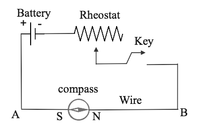
In the below figure, a wire AB is taking which is lying in the north- south direction and it is connected to a battery along with a rheostat and a tapping key. And we set up a compass needle below the wire. And now we observed that
(1) When the key is open (switch is off), no current passes through the wire, so that the needle shows no deflection, and it points in the North-South direction (along the earth's magnetic field). In this position, we can see that the needle is parallel to the wire as shown in Figure(a)
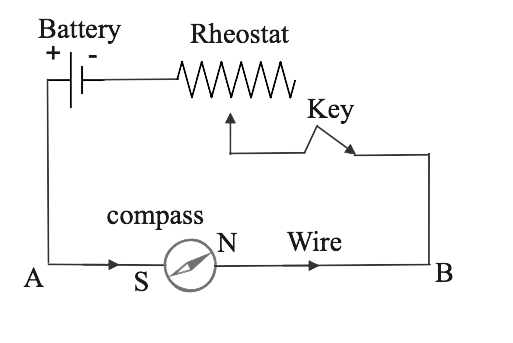
(2) In the below figure now when we press the key, a current pass through the wire which is in the direction from A to B (it means from south to north) and the north pole of the compass needle deflects towards the west direction.
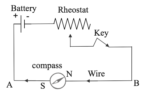
(3) Now if we reverse the direction of current in the wire, by reversing the connections at the terminals of the battery, the North Pole (N) of the needle deflects towards the east which is shown in the below figure.
(4) If the compass needle is placed just above the wire, when the direction of current in wire is from A to B, the North Pole (N) deflects towards east shown in the below figure.
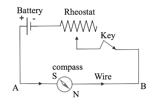
but if the direction of current in wire is from B to A, then the needle deflects towards west as in figure
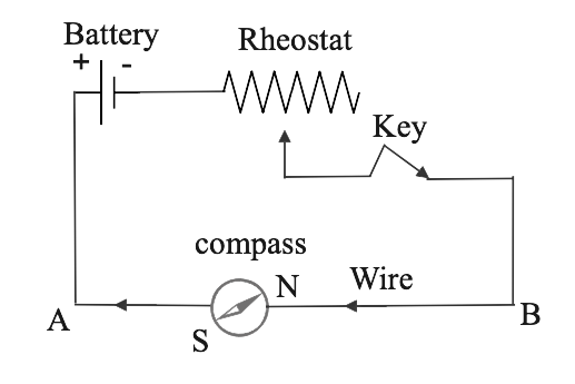
All the above observations of the experiment concluded that a current carrying wire always produces a magnetic field around it.
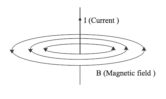
2. Draw a diagram showing the direction of three magnetic field lines due to a straight wire carrying a current. Also show the direction of current in the wire.
Ans: In the below diagram a current carrying wire is shown. We know that the direction of the magnetic field due to current carrying straight wire is determined by the right-hand thumb rule. If the thumb is along in the direction of current, then the curling fingers shows the magnetic field lines.
3. How is the magnetic field due to straight current carrying wire affected if current in the wire is (a) decreased ?
Ans: On decreasing the current the magnetic field also decreases.
The intensity of the magnetic field around the current carrying straight wire is proportional to the distance from the conductor and by the amount of current flowing through it. The magnetic field created around a current-carrying wire is very weak with a high current passing through it. So, when current is decreased the magnetic field will also decrease.
(b) reversed?
Ans: The direction of magnetic field lines will get reversed after reversing the current in the wire
The magnetic field generated is always perpendicular to the direction of the current Hence if we reverse the current the direction of magnetism also reverses because the magnetic poles get reversed.
4. State a law that determines the direction of the magnetic field around a current-carrying wire.
Ans: Right-hand thumb rule determines the direction of the magnetic field around a current-carrying wire. It states that if we hold the current-carrying conductor in the right hand such that the thumb points in the direction of flow of current, then the curled fingers encircle the wire in the direction of the magnetic field lines.
5. A straight wire lying in a horizontal plane carries a current from north to south.
(a) What will be the direction of the magnetic field at a point just underneath it
Ans: The direction of the magnetic field at a point just underneath is towards east. If we hold the current-carrying conductor in the right hand with the thumb pointing in the direction of the current flow from north to south. Then the direction of the magnetic field can be deduced by the right-hand thumb rule and it gives east direction.
(b) Name the law used to arrive at the answer in the part (a)
Ans: Right-hand thumb rule.
6. What will happen to a compass needle when the compass is placed below a wire with a needle parallel to it and a current is made to flow through the wire? Give a reason to justify your answer.
Ans: The compass needle will show deflection. We know that if a current passes through a conductor it produces a magnetic field around it due to which the compass needle gets deflected. It experiences a torque and wants to align itself in the direction of the magnetic field.
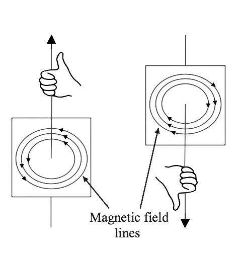
7. draw a labeled diagram showing the three magnetic field lines of a loop carrying current. Mark the direction of current and the direction of magnetic field by arrows in your diagram
Ans: Magnetic field lines of a current carrying loop: -
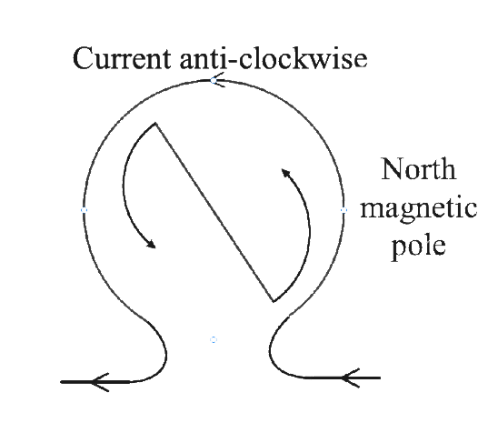
8. A wire, bent into a circle, carries a current in an anticlockwise Direction. What polarity does this face of the coil exhibit?
Ans: Face of the coil exhibits North polarity which is shown in the below figure.
9. What is the direction of the magnetic field at the centre of a coil carrying current
(i) the clockwise
Ans: When we pass the current through the coil, the direction of magnetic field at the center of the coil is along the axis of the coil. And if the current flowing through the coil is in the clockwise direction, then according to the right-hand thumb rule, the magnetic force lines at the center of the coil will be along the axis inwards
(ii) the anti-clockwise direction?
Ans: If the current flows through the coil in the anticlockwise direction, then the magnetic lines of force at the center of the coil will be along the axis outwards according to the right-hand thumb rule also.
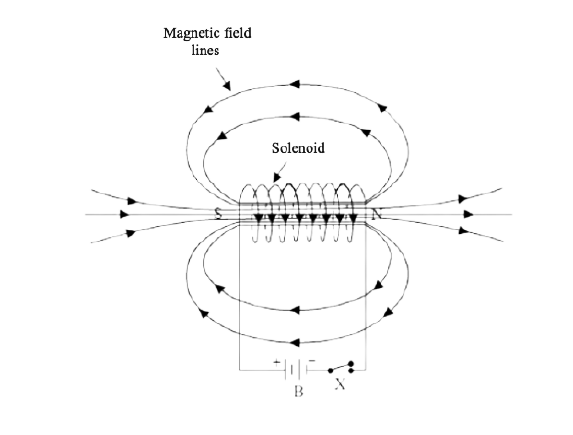
10. Draw a diagram to represent the magnetic field lines along the axis of a current-carrying solenoid. Mark arrows to show the direction of current in the solenoid and the direction of magnetic field lines.
Ans: Magnetic field lines along the axis of a current-carrying solenoid: -
11. Name and state the rule by which the polarity at the ends of a current-carrying solenoid is determined.
Ans: The polarity at the ends of a current-carrying solenoid is determined by the Right-hand thumb rule
Right-hand thumb rule: If we hold the current-carrying conductor in the right hand such that the thumb points in the direction of flow of current, then the fingers encircle the wire in the direction of the magnetic field lines.
12. The diagram in fig. 10.17 shows a small magnet placed near solenoid AB with its north pole N and near the end A. Current is switched on in the solenoid by pressing the key K.
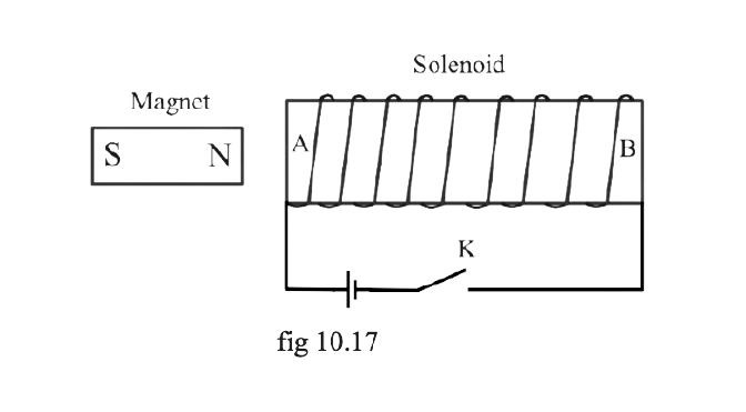
(a) State the polarity at the ends A and B.
Ans: The polarity at the end A and B is the North pole and South pole respectively.
(b) will the magnet be attracted to repel? Give a reason for your answer.
Ans: The magnet will be repelled because we know that as current at the face (A end side of the solenoid) is anticlockwise, the end of the solenoid near the north pole of the magnet becomes the north pole and it repels the north pole of the magnet.(two like poles repel to each other).
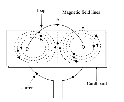
13. The diagram in fig. 10.18 It shows the spiral coil bound on a hollow cardboard tube AB. A magnetic compass is placed close to it. Current is switched on by closing the key.
(a) What will be the polarity at the end A and B
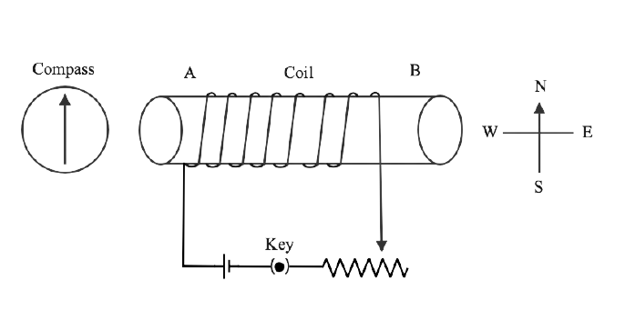
Ans: The polarity at the end A and B is North pole and South pole respectively.
(b) How will the compass needle be affected? Give a reason.
Ans: The north pole of the compass needle will deflect which is in the west direction. The end of coil A behaves like the north pole so that it repels the north pole of the compass needle towards the west direction.
14. State two ways by which the magnetic field due to a current-carrying solenoid can be made stronger.
Ans: The magnetic field due to a current-carrying solenoid can be made stronger by using these methods-
(i) If we increase the number of turns(n) in the winding of the solenoid then this will increase its magnetic field.
(ii) If we increase the current through the solenoid, it will increase its magnetic field.
15. Why does a current-carrying freely suspended solenoid rest along a particular direction? State the direction in which it rests.
Ans: We know that a current-carrying freely suspended solenoid at rest behaves like a bar magnet. So that it rests along a particular direction and this direction will be the geographic north-south direction.
16. What effect will there be on a magnetic compass when it is brought near a current-carrying solenoid?
Ans: When a magnetic compass is brought near a current-carrying solenoid, the needle of the compass will rest in the direction of the magnetic field due to the solenoid at that point.
17. How is the magnetic field due to a solenoid carrying current affected if a soft iron bar is introduced inside the solenoid?
Ans: When a soft iron bar is inserted inside a solenoid then the strength of the magnetic field increases because due to magnetic induction the iron ore gets magnetized.
18. Complete the following sentences:
(a) When current flows in a wire, it creates ............
Ans: When current flows in a wire, it creates a magnetic field around it.
(b) On reversing the direction of current in a wire, the magnetic field produced by it gets ………...
Ans: On reversing the direction of current in a wire, the magnetic field produced by it gets reversed.
(c) A current-carrying solenoid behaves like a ..............
Ans: A current-carrying solenoid behaves like a bar magnet.
(c) A current carrying solenoid when freely suspended, it always rests in .......... direction.
Ans: A current carrying solenoid when freely suspended, it always rests in a north - south direction.
19. You are required to make an electromagnet from a soft iron bar by using a cell, an insulated coil of copper wire and a switch. (a) Draw a circuit diagram to represent the process. (b) Label the poles of the electromagnet.
Ans: - circuit diagram is shown in below figure -
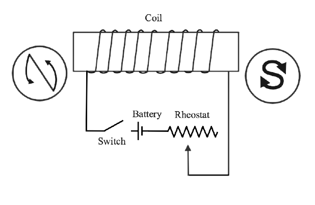
20. The diagram in fig. 10.19 shows a coil wound around a soft iron bar XY. (a) State the polity at the ends X and Y as the switch is pressed.
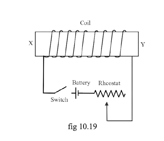
Ans: The polarity at the end X and Y is North pole and South pole respectively.
(b) Suggest one way of increasing the strength of electromagnet so formed.
Ans: By increasing the current, we can increase the strength of the electromagnet. For that we reduce the resistance of circuit by mean of rheostat to increase current
21. (a)What name is given to a cylindrical coil of diameter less than its length?
Ans: Solenoid is a cylindrical coil whose length is greater than its diameter.
(b) If a piece of soft iron is placed inside the coil mentioned in part (a) and current is passed in the point from a battery, what name is then given to the device so obtained?
Ans: If a piece of soft iron is placed inside the coil and current is passed in the point from a battery it forms an electromagnet. So, the device obtained is electromagnet.
(c) Give one use of device mentioned in part (b).
Ans: It is used in Motors and generators.
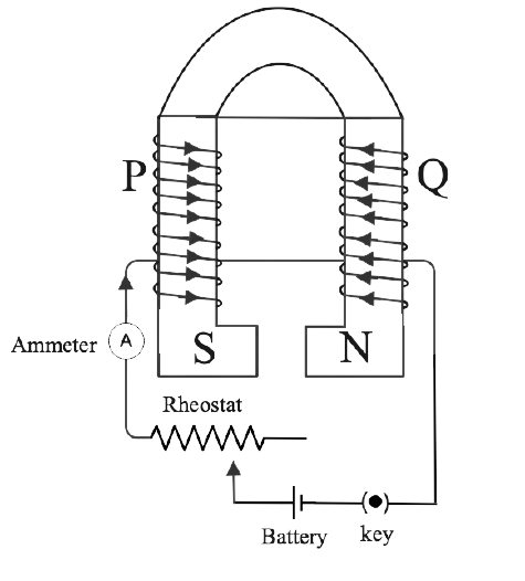
22. Show with the aid of a diagram how a wire is wound on a U-shaped piece of soft iron in order to make it an electromagnet. Complete the circuit diagram and label the poles of the electromagnet.
Ans: Electromagnet is made by passing electric field or current through the iron. The circuit diagram is shown below.
23. What is an electromagnet? Name two factors on which the strength of magnetic field of an electromagnet depends and state how it depends on the factors stated by you.
Ans: An electromagnet is a temporary strong magnet in which the magnetic field is produced by an electric current flowing through the coil wound around the piece of soft iron. For that, it is connected to a battery or power supply. A current through the coil creates a magnetic field around the wire.
The strength of the magnetic field of an electromagnet depends on the below factors:
(i) Number of turns in the Winding: The strength of the magnetic field increases on increasing the number of turns of winding in the solenoid of the electromagnet.
(ii) Current: The strength of the Magnetic field increases on increasing the current passing through the coil in the electromagnet.
24. Fig. 10.20 shows the current flowing in the coil of wire wound around the soft iron horse shoe core.
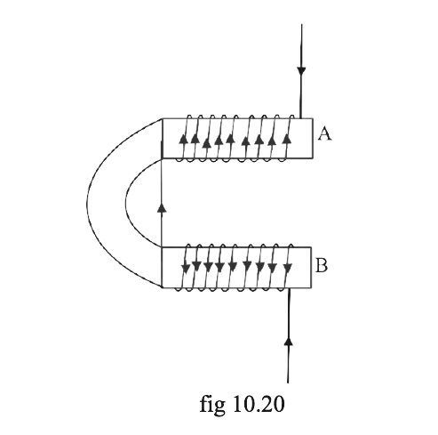
(a) State the polarity developed at the ends A and B
Ans: At A-south pole and at B-north pole.
(b) How will the polarity at the ends A and B change on reversing the direction of current.
Ans: On reversing the direction of current, the polarities of end A and B get reversed. So at the A- north pole and at the B-south pole developed.
(c) Suggest one way to increase strength of magnetic field produce.
Ans: By increasing the current through the coil, we can increase the strength of the magnetic field produced.
25. State two ways by which the strength of an electromagnet can be increased.
Ans: The strength of an electromagnet can be increased or improved by below ways:
(i) By increasing the number of turns of winding in the solenoid we can increase the strength of an electromagnet.
(ii) We can make the electromagnet stronger by increasing the current through the solenoid.
26. Name one device that uses an electromagnet.
Ans: Electric generators and motors are the devices that use an electromagnet.
27. State two advantages of an electromagnet over a permanent magnet.
Ans: The advantages of electromagnets are mentioned as below:
An electromagnet can produce a strong magnetic field, so it is advantageous over permanent magnets.
The strength of the magnetic field of an electromagnet can easily be changed by the varying current in its solenoid. So we can increase or decrease its strength according to our convenience by changing current.
28. State two differences between an electromagnet and a permanent magnet.
Ans:
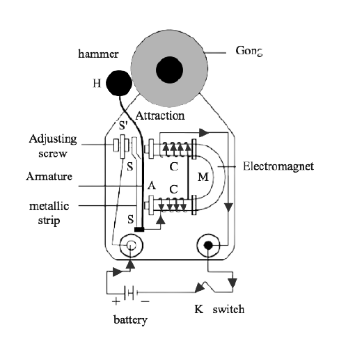
29. Why is soft iron used as the core of the electromagnet in an electric bell ?
Ans: Soft iron is used for making electromagnets because soft iron is a special kind of magnetic material and the soft iron bar acquires the magnetic properties only when an electric current flows through the solenoid and it gets easily magnetized. But when the current switch is off, it loses the magnetic properties meaning when the field is removed, it loses its magnetism. That's why we choose or use soft iron for the making core of the electromagnet in an electric bell.
30. How is the working of an electric bell affected if alternating current is used instead of direct current?
Ans: If an a.c. source is used in place of battery i.e., direct source of current, the core of electromagnet will get magnetized, but the polarity at its ends will change. We know that attraction of armature does not depend on the polarity of the electromagnet, so that the bell will still ring on pressing the switch k.
31. The incomplete diagram of an electric bell is given in fig. 10.21. Draw winding of coil on the core and complete the electric circuit in the diagram
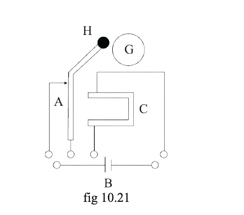
G - Gong
H - Hammer
A - Armature
C -Core
B - Battery
Ans: Complete diagram of an electric bell is given below with winding of coil and proper electric circuit-
32. Name the material used for making the armature of an electric bell give reason for your answer.
Ans: Soft iron is used for making the armature of an electric bell because the soft iron is a special kind of magnetic material which can induce magnetism rapidly.
Multiple Choice Type
1. The presence of magnetic field at a point can be detected by mean of :
(a) a strong magnet
(b) a solenoid
(c) a compass needle
(d) a current carrying wire
Ans: Option (c) is the correct answer.
In the presence of a magnetic field, the compass needle rests only in the direction of the magnetic field So that the presence of a magnetic field at a point can be detected by a compass needle.
2. On reversing the direction of current in a wire the magnetic field produced by it:
(a) gets reversed in direction
(b) increase in strength
(c) decrease in strength
(d) remains unchanged instant and direction
Ans: Option (a) is the correct answer.
If the direction of current in a wire is reversed, the polarity of the faces of the wire also reverses so that the magnetic field produced by it gets reversed in direction.
Exercise 10 (B)
1. Name three factors on which the magnitude of force on a current carrying conductor placed in a magnetic field depends and state how does the force depends on factors by you.
Ans: We know that the force on a current-carrying wire or a conductor placed in a magnetic field is F = IlB sin θ. The magnitude of force on a current carrying conductor depends on these three factors directly when it is placed in a magnetic field are given below:
(i) magnetic field strength B.
(ii) Current I flowing in the conductor or wire.
(iii) On length of conductor or a wire.
2. State condition in each case for a magnitude of force on a current carrying conductor placed in a magnetic field to be (a) zero.
Ans: We know that the force on a current-carrying wire or a conductor placed in a magnetic field is F = IlB sin θ.
When the current in the conductor is in the direction of the magnetic field, the angle between l and B is zero (θ is zero) and sinθ is also zero. Hence, magnetic force will be zero.
(b) State condition in each case for a magnitude of force on a current carrying conductor placed in a magnetic field to be maximum.
Ans: When current I in the conductor is perpendicular to the magnetic field B. So, the angle between l and B is 90 degrees (θ is 90) and sinθ is also one. Hence, magnetic force will be maximum in this case.
3. How will the direction of force be changed, if the current is reversed in the conductor placed in a magnetic field?
Ans: If the current is reversed in the conductor placed in a magnetic field, Direction of force is also reversed.
According to Fleming's Left-Hand Rule, the middle finger in the direction of the current, then, the thumb points in the direction of the force exerted on the conductor placed in the magnetic field. So, the direction of force is also reversed if the current is reversed in the conductor placed in a magnetic field.
4. Name and state the law which is used to determine the direction of force on the current carrying conductor placed in a magnetic field.
Ans: Fleming's left hand rule is used to determine the direction of force on the current carrying conductor placed in a magnetic field.
Fleming's left hand rule: when we Stretch the forefinger, middle finger and the thumb of your left hand mutually perpendicular to each other. If the forefinger indicates the direction of magnetic field and the middle finger indicates the direction of current, then the thumb will indicate the direction of motion of the conductor.
5. State Fleming's left hand rule.
Ans: Fleming's left hand rule: Stretch the forefinger, middle finger and the thumb of your left hand mutually perpendicular to each other. If the forefinger indicates the direction of magnetic field and the middle finger indicates the direction of current, then the thumb will indicate the direction of motion of the conductor.
6. State the unit of magnetic field in terms of the force experienced by a current carrying conductor placed in a magnetic field.
Ans: We know that the force on a current-carrying wire or a conductor placed in a magnetic field is F = IlB sin θ.
B = F/Ilsin θ. (sin θ is a number that has no unit)
Unit is: Newton/(ampere * meter) or (NA-1m-1).
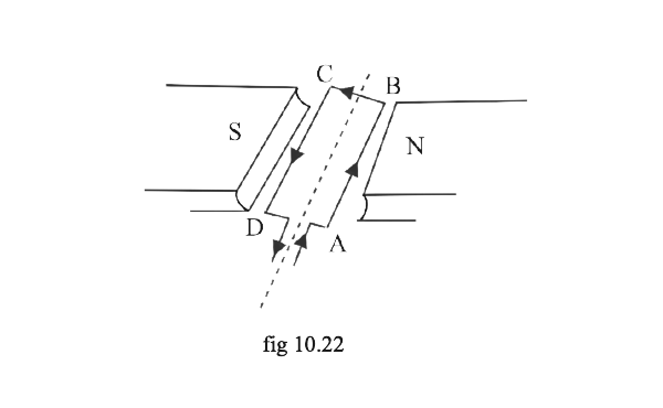
7. A flat coil ABCD is freely suspended between the poles of a U-shaped permanent magnet in the plane of the coil parallel to the magnetic field.
(a) What happens when a current is passed in a coil?
Ans: When a current is passed in a coil, the coil will experience a torque so that it will rotate.
(b) When will the coil come to rest?
Ans: When the plane becomes perpendicular to the magnetic field, the coil will come to rest.
(c) When will the couple acting on a coil be
(i) maximum, and (ii) minimum?
Ans: (i) When the plane of a coil is parallel to the magnetic field, the maximum couple acts on the coil.
(ii) When the plane of the coil is perpendicular to the magnetic field, a minimum couple acts on the coil.
(d) Name and instrument which makes use of the principle stated above.
Ans: D.C. motor is the instrument that makes use of the above principle.
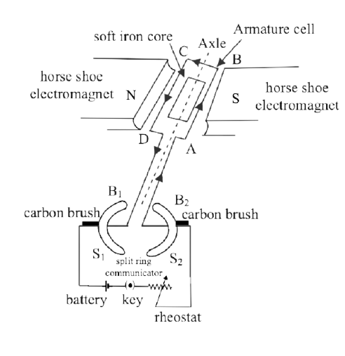
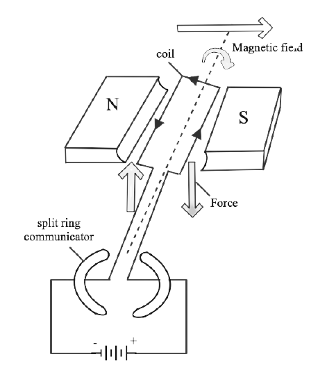
8. A coil ABCD mounted on an axle is placed between the poles N and S of a permanent magnet as shown in figure 10.28.
(a) In which direction will the coil begin to rotate when current is passed through the coil in direction ABCD by connecting a battery between the ends A and B of the coil?
Ans: Current is passed through the coil by connecting the battery between the coil, The coil begins to rotate when current passes through it and it is in an anticlockwise direction.
(b) Why is commutator necessary for the country's rotation of the coil?
Ans: This is because, after half rotation, the arms AB and CD get interchanged, so the direction of torque on the coil reverses. To keep the coil rotating in the same direction, a commutator is needed to change the direction of current in the coil after each half rotation of the coil.
(c) Complete the diagram with a commutator, etc. for the flow of current in the coil.
Ans:
9. What is an electric motor? state its principle.
Ans:
Electric Motor: An electric motor is a device that converts electrical energy into mechanical energy.
Principle: An electric motor /dc motor works on the principle that when an electric current is passed through a conductor (rectangular coil) which is placed in a magnetic field, and current is passed through it, a force acts on the conductor as a result of which the conductor or coil begins to move or rotate continuously.
10. Draw a labelled diagram of a d.c. motor showing its main parts.
Ans:
11. What energy conversion takes place during the working of a DC motor?
Ans: A dc motor converts the electrical energy into mechanical energy.
12. State two ways by which the speed of rotation of an electric motor can be increased.
Ans: The speed of rotation of an electric motor can be increased by following:
(i) By Increasing the current.
(ii) By Increasing the number of turns in the coil of an electric motor.
13. Name two applications in which an electric motor is used
Ans: Electric motor is used in electrical gadgets which is given below-
(i) Washing machine
(ii) Juicer, grinder and mixer etc.
Multiple Choice Type
1. In an electric motor the energy transformation is:
(a) from electrical to chemical
(b) from chemical to light
(c) from mechanical to electrical
(d) from electrical to mechanical
Ans: Option (d) is correct.
An electric motor is a device which converts Electrical energy into mechanical energy.
Exercise - 10 (C)
1. (a) What is an Electromagnetic Induction
Ans: Michael Faraday discovered electromagnetic induction. Electromagnetic or magnetic induction is the production of an emf. In a changing magnetic field (by change in number of magnetic field lines associated with conductor), an electromotive force is developed between the ends of the conductor.
(b) Describe an experiment to demonstrate the phenomenon of electromagnetic induction.
Ans: In the below figure -
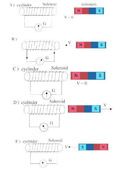
In Fig. (a) we can see that when the magnet is stationary (v = 0) there is no deflection in the galvanometer. The pointer read zero deflection.
Now if we move the magnet's north pole towards the solenoid, which is shown in Fig (b), then the galvanometer shows a deflection towards the right side, and the direction of current shown in the diagram.
As the motion of the magnet stops again, the velocity of the magnet is zero, then no deflection occurs in the galvanometer and the pointer comes to the zero position. Fig (c) shows that no current is flowing in this condition.
It is concluded that the current in the solenoid flows as long as the magnet is moving.
Now, If the magnet is moved away from the solenoid, which is shown in the figure Fig. (d). The current again starts to flow in the solenoid, but in an opposite direction to the previous case which is shown in Fig. (b) so that the pointer of the galvanometer deflects towards the left side.
If we move the magnet away from the solenoid but with more velocity then the direction of deflection remains the same, but the extent of deflection increases. Because more current flows in the circuit.
In Fig.(e) it is shown that if we change the polarity of the magnet and then the magnet is brought towards the solenoid, so the deflection of galvanometer towards left because the current in solenoid flows in the direction opposite to the previous one shown in Fig (b)
2. State faraday’s law of electromagnetic induction.
Ans: Faraday's gives two laws of electromagnetic induction which is explained below:
First law - Whenever there is a change in the magnetic flux linked with a coil, an e.m.f. or electromotive force is induced. The induced e.m.f. lasts so long as there is a change in the magnetic flux linked with the coil. If the conductor circuit is closed, a current is induced, which is called induced current.
Second law - The magnitude of the induced e.m.f. is directly proportional to the rate of change of the magnetic flux linked with the coil.
e = -N(dΦ/dt)
Here e = induced voltage
N = number of loops
dΦ = change in magnetic flux
dt = change in time
And if the rate of change of magnetic flux remains uniform, then a steady e.m.f. is induced.
3. State two factors on which the magnitude of induced e.m.f. In a coil depends.
Ans: Magnitude of induced e.m.f e = -N(dΦ/dt) in a coil depend upon:
(i) The change in the magnetic flux (dΦ).
(ii) The time in which the magnetic flux changes (dt).
4. (a) What kind of energy change takes place when a magnet is moved towards a coil having a galvanometer between its end?
Ans:
(a) When a magnet is moved towards a coil having a galvanometer between its end, mechanical energy changes to electrical energy.
(b) Name the phenomena.
Ans: Electromagnetic induction is the Phenomenon which is placed in the given question.
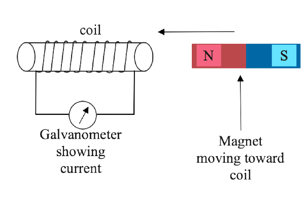
5. (a) How would you demonstrate that mandatory current can be obtained by the suitable use of a magnet, a coil of wire and a galvanometer?
Ans: In the below diagram it is shown that by moving the magnet towards the coil which is connected to the galvanometer a current is produced in the circuit.
We know that if a relative motion between the coil and the magnet occurs, there is a change in magnetic flux linked with the coil. According to the law of faraday due to this change in the magnetic flux of the coil, an e.m.f. Or electromotive force is induced in the coil. And if the circuit is closed, then the current will flow in the coil.
(b) What is a source of energy associated with the current obtained in part (a)?
Ans: Mechanical energy is associated with the current obtained in part (a).
6. (a) Describe briefly one way of producing an induced EMF.
Ans: One way of producing an induced e.m.f.-

In the Fig. (a) we can see that when the magnet is stationary (v = 0) there is no deflection in the galvanometer. The pointer read zero deflection.
Now if we move the magnet's north pole towards solenoid, which is shown in Fig (b), then the galvanometer shows a deflection towards the right side and the direction of current shows in the diagram.
As the motion of the magnet stops again, the velocity of the magnet is zero, then no deflection occurs in the galvanometer and the pointer comes to the zero position. Fig (c) shows that no current is flowing in this condition.
It is concluded that the current in the solenoid flows as long as the magnet is moving.
Now if the magnet is moved away from the solenoid, which is shown in the figure Fig. (d). The current again starts to flow in the solenoid, but in an opposite direction to the previous case which is shown in Fig. (b) so that the pointer of the galvanometer deflects towards the left side. Therefore, by the mutual movement of magnet and coil, we can induce e.m.f.
(b) State one factor that determines the magnitude of induced EMF in part (a) above.
Ans: Magnitude of induced e.m.f depends upon the factor magnetic flux. If there is a change in magnetic flux, then it will change the magnitude of produced e.m.f.
(c) What factors determine the direction of induced EMF and part (a) above?
Ans: The direction of induced e.m.f depends on the magnitude of magnetic flux whether it is increasing or decreasing.
7. Complete the following sentence:
The current is induced in a closed circuit only if there is ………………..
Ans: The current induced in a closed circuit only if there is change in magnetic flux linked with the circuit.
By changing magnetic flux or number of magnetic field lines an e.m.f. Is induced and if the circuit is closed then a current is included in it.
8. In which of the following cases e.m.f. is induced?
(i) A current is started in a wire held near a loop of wire.
(ii) The current is switched off in a wire held near the loop of wire.
(iii) The magnet is moved through a loop of wire loop.
(iv) A loop of wire is held near a magnet.
Ans: In case (i)(ii) and (iii), a e.m.f. Is induced.
9. A conductor is moved in a varying magnetic field. Name the law which determines the direction of current induced in a conductor.
Ans: Fleming's right hand rule determines the direction of current induced in the conductor.
10. State Fleming's right-hand rule
Ans: Fleming's right-hand rule: When we Stretch the forefinger, middle finger, and the thumb of our right hand mutually perpendicular to each other. If the forefinger indicates the direction of the magnetic field and the thumb indicates the direction of motion of the conductor, then the middle finger indicates the direction of induced current.
11. What is Lenz's law?
Ans: Lenz's law: It states that the direction of induced e.m.f. (or induced current) is such that it always tends to oppose the cause which produces it. In other words, the direction of an induced current is always such as to oppose the change in the circuit or the magnetic field that produces it.
E.m.f. = e = - N(dΦ/dt)
Here e = induced voltage, N = number of loops, dΦ = change in magnetic flux, dt = change in time
And in the formula, the negative sign is contributed from Lenz’s law.
12. Why does it become more difficult to move a magnet towards a coil when that number of turns in the coil has been increased?
Ans: When the number of turns in the coil is increased, then the magnitude of induced e.m.f. in the coil becomes more, and then by Lenz's law the force opposing the motion also increases. so that it is difficult to move a magnet towards the coil.
13. Explain why an induced current must flow in such a direction so as to oppose the change producing it.
Ans: According to Lenz law an induced current must flow in such a direction so as to oppose the change producing it. For producing this change, spent mechanical energy is transformed into electrical energy in the form of induced current for conservation of energy.
14. Explain how Lenz's law shows the conservation of energy in the phenomenon of electromagnetic induction.
Ans: Lenz's law shows the law of conservation of energy. It shows that the mechanical energy spent in doing work for producing this change, against the opposing force which is experienced by the moving magnet, is transformed into electrical energy in the form of induced current in the solenoid for conservation of energy.
15. The diagram in figure 10.42 shows a coil of several turns of copper wire near the magnet and is the coil is moved in the direction of arrow shown in the diagram
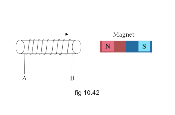
(i) In what direction does the induced current flow in the coil?
Ans: From the diagram, it is shown the coil is bringing towards the magnet, the north pole generates near this end of the coil so that current starts flowing from A to B.
(ii) Name the low used to arrive at the conclusion in part (i)
Ans: Lenz’s law
(iii) How would the current in the coil be altered if
(a) The coil has twice the number of turns.
Ans: We know that induced Current is directly proportional to the number of turns in the coil, therefore if we twice the number of turns in the coil, the current will also become two times
(b) The coil was made to move three times faster ?
Ans: If we move the coil more like three times faster then the current becomes thrice because mutual movement between magnet and coil is directly proportional to induced current.
16. The diagram in figure 10.43 shows a fixed coil of several turns connected to a Centre zero Galvanometer G and a magnet NS which can move in the direction shown in the diagram
(a) Describe the observation is a galvanometer if
(i) the magnet is moved rapidly,
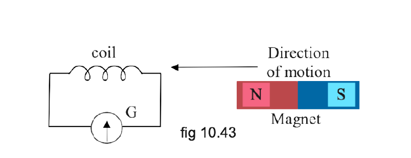
Ans: When the magnet is moved rapidly as in the direction shown in the given figure, there is current induced due to this motion so deflection occurs in the galvanometer and the pointer deflects towards the right side.
(ii) the magnet is kept stationary after it has moved into the coil.
Ans: If the magnet is kept stationary after it has moved into the coil, There will be no deflection in the galvanometer as there is no change in flux because of no mutual movement between coil and magnet.
(iii) the magnet is then rapidly pulled out of the coil.
Ans: If the magnet is then rapidly pulled out of the coil, the direction of induced current is opposite to the previous case so deflection in the galvanometer is on the left side so that the pointer deflects towards the left.
(b) How would the observation in (i) of part (a) change if a more powerful magnet is used?
Ans: If a more powerful magnet is used, deflection occurs in the galvanometer on the right side and increases in magnitude.
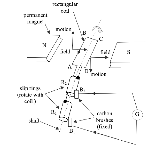
17. Name and State the principle of a simple a.c. generator. What is its use?
Ans: Electric generators are machines that convert mechanical energy into electrical energy, and it works on the principle of 'electromagnetic induction'. Principle - Whenever a coil is rotated in a magnetic field, the magnetic flux linked with the coil changes, and therefore, an EMF is induced between the ends of the coil and if the circuit is closed then induced current will flow in the circuit through the coil. Therefore, a generator acts like a source of current Hence, the generator generates an electric current due to induced emf.
Uses - This simple a.c. The generator is used in receptions, functions, malls, factories, houses, etc because of the alternating current produced by the generator. It has high transmission power and power generation capability.
18. What determines the frequency of AC produced in a generator?
Ans: The frequency of AC produced in a generator is determined by the rotation of the coil in one second or the speed of rotation of the coil and is equal to the frequency of rotation of the coil.
19. complete the sentence:
An a.c. generators change the energy ………….. to ……….. energy.
Ans: An a.c. the generator changes the energy mechanical to electrical energy.
20. Draw a labelled diagram of a simple a.c. generator.
Ans:
21. In an a.c. generator, the speed at which the coil rotates is doubled. how would this affect
(a) the frequency of output voltage
Ans: The frequency of an AC generator is depending on the speed of the rotation of the coil. It is mentioned in the question that the speed rotation of a coil is doubled, then frequency is also doubled.
(b) the maximum output voltage
Ans: In an a.c. generator, if the speed rotation of a coil is doubled, then maximum output voltage is also doubled.
22. State two ways to produce a higher e.m.f. In an a.c. generator.
Ans: There are ways to produce a higher e.m.f. in an a.c generator. Two ways are given below:
If we increase the speed of rotation of the coil, then there will be an increase in the e.m.f. produce.
Number of turns of coil is another parameter that induces e.m.f. Depends on it.
By increasing the number of turns of the coil then we will produce a higher e.m.f. In an a.c. generator.
23. What energy conversion does take place in the generator when it is in use.
Ans: When the generator is in use the mechanical energy is converted to electrical energy.
24. State (i) two dissimilarities and (ii) two similarities between a d.c. motor and a.c. generator.
Ans: Two dissimilarities or differences between D.C. motor and A.C. generator:
Similarity: Both in A.C generator and D.C motor, a coil rotates in a magnetic field between the pole pieces of a powerful electromagnet.
25. State one advantage of using an a.c. over the d.c.
Ans: The cost of production of alternative current is less than the DC system. So it is an advantage of a.c. source over d.c. And a.c. devices are more simple than d.c. and do not need much maintenance and repairs during their operation.
26. For what purpose are the Transformers used? On which type of current do transformers work?
Ans: The purpose of the transformer is to step up (increase) or step down (decrease) the a.c. voltage. A transformer works on an alternating current source.
27. State two factors on which the magnitude of an induced e.m.f. in the secondary coil of a transformer depends.
Ans: The magnitude of the induced emf in the secondary coil of the transformer depends on factors which is given below:
By the formula ES/EP = NS/NP
S stands for secondary coil and P stands for primary coil. We can see that the emf of the second coil depends on the ratio of the number of turns in the secondary coil to the number of turns in the primary coil in the transformer.
By the above formula ES, the emf of the secondary coil also depends on the emf of the primary coil which is applied to it.
28. How are the e.m.f. in the primary and secondary coils of a transformer related with the number of turns in these coils?
Ans: The relation is following:
ES/EP = NS/NP
S stands for secondary coil and P stands for primary coils.
ES = emf induced in the secondary coil
EP = emf given to the primary coil
NS = number of turns in the secondary coil
NP = number of turns in the primary coil
29. Draw a labelled diagram to show the various components of a step up transformer.
Ans: Labelled diagram of a step-up transformer is below -

30. Name the device used to Transform 12-volt a.c. to 200-volt a.c. name the principle on which it works.
Ans: To transform 12-volt a.c. to 200-volt a.c we used a step-up transformer. Because in the step-up transformer, it increases or steps up the voltage. And it works on electromagnetic induction.
31. Draw a labelled diagram of a step-up transformer and explain how does it work. State two characteristics of the primary coil as compared to its secondary coil.
Ans: Labelled diagram of a step-up transformer -

Working - The step-up transformer is used to exchange a low voltage alternating e.m.f. to a high voltage alternating e.m.f. of equal frequency.
When the primary coil is connected to the alternating e.m.f. source, varying current flows through the primary circuit so it produces a varying magnetic field in the core of the transformer. Thus, this induces an e.m.f. in the secondary coil because there is change in the magnetic field lines linked with the secondary coil. The induced e.m.f. varies with applied e.m.f. in the primary coil. The magnitude of e.m.f. induced in the secondary coil depends on the turns ratio (NS/NP) and the magnitude of the applied e.m.f. through the primary coil. For a transformer this relation is given by -
ES/EP = NS/NP
S stands for secondary coil and P stands for primary coils.
ES = emf induced in the secondary coil
EP = emf given to the primary coil
NS = number of turns in the secondary coil
NP = number of turns in the primary coil
Two characteristics of the primary coil as compared to its secondary coil are given below -
The primary coil has less than the number of turns with comparison to the secondary coil.
Primary coil uses a thicker wire in comparison to the secondary coil.
32. Draw a labelled diagram of a device you would use to transform 200 volt a.c. to 15 volt a.c. Name the device and explain how it works. Give its two uses.
Ans: The device is a step down transformer. And labelled diagram of step down transformer is below -
Working: In a stepdown transformer, the number of turns in the secondary coil are less than the number of turns in the primary coil. So, NS< NP
We know that the turn ratio of a transformer is NS/NP
i.e., turns ratio n<1 or NS/NP <1.
By formula - ES/EP = NS/NP
So the ratio of Es/Ep is also less than one(Es/Ep<1) means induced e.m.f. in secondary coil is less than e.m.f. in primary coil.
Two uses of the step-down transformer are:
In welding machines, it is used.
To step down the voltage in the power substations before its distribution to the customers.
33. Name the coil of which the wire is thicker in a
(i) Step Up,
Ans: In case of a step-up Transformer thicker wire is used in the primary coil as compared to that in the secondary coil.
(ii) Step down Transformer. Give reason to your answer.
Ans: In a step-down Transformer the wire in the secondary coil is thicker than in the primary coil.
We know that Step up transformers are used to convert low voltage to high voltage. For attending high voltage, the secondary coil current should be low (is <ip). We know that resistance is inversely proportional to the cross-sectional area. By using thicker wire, we can reduce the resistance so that we can reduce the loss of energy (heat energy) also in the coil. The reverse of it happens in the case of a step-down transformer.
34. (a) Complete the following diagram in fig. 10.44 of a transformer and name the part label A and B.
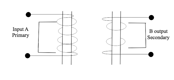
Ans: (a) Complete diagram of a transformer -
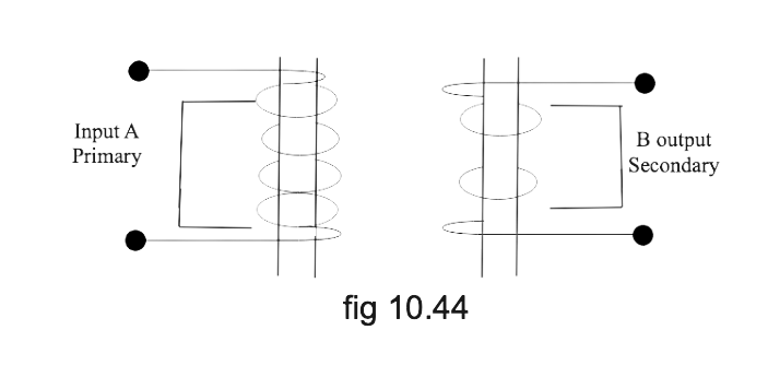
(b) Name the part you have drawn to complete a diagram in part (a).
Ans: part A is the primary coil and part B is the secondary coil.
(c) What is the material of the part named above?
Ans: We have drawn a laminated core in the above diagram. Soft iron is used for making the core part of the transformer.
(d) In this transformer is step up or step down? Give a reason.
Ans: We can see from the diagram that the primary coil has a large number of turns and the secondary coil has less number of coils and the voltage is decreased so it is a step-down transformer.
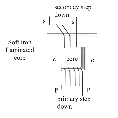
35. The diagram in fig. 10.45 shows the core of a transformer and its input and output connection.
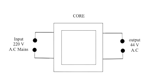
(a) State the material used for the core and describe its structure.
Ans: Soft iron is used in the core part of the transformer. This core is made up of thin laminated sheets in the shape T and U shape. And placed one above the other and insulated from each other. For that, we can paint or varnish coating over them. The advantage of this core part is that it prevents the formation of eddy currents and thus reduces energy losses.
(b) Complete the diagram of the Transformer and connection by lapping all parts joined by you.
Ans:
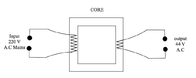
(c) Name the Transformer: step up and step down?
Ans: We can see from the diagram that the primary coil has a large number of turns and the secondary coil has less number of coils and the voltage is decreased so it is a step-down transformer.
36. The output current of a transformer in which the voltage is stepped down is usually higher than the input current. explain why.
Ans: Step-down transformer converts higher voltage to lower voltage. If it is an ideal transformer, input power is equal to the output power
By formula of power = P = I V
As in the step-down transformer the voltage decreases. By the above formula, the current should be increased to get the same initial power as there is no energy loss.
37. Why is the iron core of a transformer made laminated (thin sheets) instead of being in one solid piece?
Ans: The laminated iron core prevents the formation of eddy currents and thus reduces losses due to eddy currents.
38. Complete the following sentences:
(i) In a step up Transformer, the number of turns in the primary are …….. than the number of turns in secondary.
Ans: In a step-up Transformer, the number of turns in the primary are less than the number of turns in secondary.
(ii) The Transformer is used in ……….. current circuits
Ans: The Transformer is used in alternating current circuits.
(iii) In a transformer, the frequency of AC voltage ……………..
Ans: In a transformer, the frequency of AC voltage remains the same.
39. How do the input and output powers in a Transformer compare? state the assumption made.
Ans: We know that in an ideal transformer, there is no loss of energy, so the output power is equal to input power.
Power in secondary coil = power in primary coil
But in an actual transformer, Input and output powers in the transformer are a little different. And there is some loss of the energy due to the resistance of the windings of the primary coil and secondary coil so that the output power is less than the input power.
40. Name two kinds of energy losses in a transformer. How are they minimized?
Ans: The energythe losses in a transformer are Copper loss and Eddy Current Loss.
We know that Primary and secondary coils of a transformer are generally made of copper wire a which has resistance so when current flows through these copper wires, there will be loss of energy in the form of heat. This Loss of energy through the windings of the transformer is known as copper loss. And it can be minimized by using thick wires in the windings of the coil in the transformer. We know ththe at resistance can be reduced by increasing the cross sectional area of wire. Therefore use of thick wire reduces its resistance and therefore reduces the copper loss .
The eddy current loss is minimized by creating the core part with thin laminations. So that minimum energy loss can occur in the transformer.
41. Give two points of difference between a step up and a step down transformer.
Ans:
42. Name the material of the core in (a) an electrical bell, (b) electromagnet, (c) a d.c. motor, (d) an a.c. generator, and (e) a transformer.
Ans: The material used in the core of an electric bell, electromagnet, a d.c. motor, an a.c. generator, and a transformer is the soft iron.
We know that soft iron shows magnetism or magnetic property when current flows in the surrounding coil.
43. Name the Transformer used in the (i) power generating station. State the function of each transformer.
Ans: (i) Step-up transformer is used in the power generating station.
In the power generating station of the power plant, a step up transformer is used. And the current which is transmitted by it is alternating current or a.c. current.
(ii) Name the Transformer used in the power substation. State the function of each transformer.
Ans: Step-down transformer is used in the power substation.
At the power substation, when its distribution to the consumers is started the voltage should be stepped down. We know that The transformer changes their incoming voltage and current and the outgoing voltage and current relationships . And it is rated by their voltage relationship i.e. primary and secondary voltages and their capacity of carrying the power.
The function of the step - up transformer - It is used in transmission lines for transforming the high voltage to low voltage.
The function of the step - down transformer - It is used in a power distribution and for controlling the home appliances.
Multiple Choice Type
1. The direction of the induced current is obtained by:
(a) Fleming's left-hand rule
(b) Clock rule
(c) Right Hand Thumb Rule
(d) Fleming's right-hand rule
Ans: Option (d) is the correct answer.
The direction of the induced current is obtained by Fleming's right-hand rule.
2. In a step-up transformer:
(a) NS = NP
(b) NS < NP
(c) NS > NP
(d) nothing can be said.
Ans: Option (c) is the correct answer.
In a step-up Transformer, the number of turns in the primary is less than the number of turns in secondary.
Numericals
1. The magnetic flux through a coil having 100 turns decreases from 5 Milli Weber to zero in 5 seconds. Calculate the e.m.f. induced in the coil.
Ans: Given - flux is decreased from 5 million weber to zero
Change in flux = 0.005 - 0 = 0.005 weber
number of turns = 100
Time = t = 5 sec
Induced emf in the coil = number of turns × rate of the change in magic flux
E.m.f = 100 × (0.005/5)
E.m.f = 100 × (0.001) = 0.1 V
E.m.f. induced in the coil = 100 millivolt
2. The primary coil of a transformer has 800 and the secondary coil has 8 turns. it is connected to 220 V a.c. supply. What will be the output voltage ?
Ans: Given: No. of turns in primary coil = Np = 800
No. of turns in secondary coil = Ns =8.
Input supply voltage = Ep = 220 V.
Relation: ES/EP = NS/NP
S stands for secondary coil and P stands for primary coil.
E.m.f. In secondary coil = output voltage = ES = (NS/NP)EP
ES = (8/800) × 220
ES = (1/100) × 220
ES = 220/100 = 2.2 volt
3. A transformer is designed to give a supply of 8 V to ring a house - bell from 240-volt a.c. mains. The primary coil has 4800 turns. How many turns will be in the secondary coil?
Ans: given - Input ac voltage Ep = 240 V.
Number of turns in primary coil Np = 4800
No. of turns in secondary coil Ns =?
Output voltage Es = 8 V.
We know that -
\[\frac{E_{S}}{E_{P}} = \frac{N_{S}}{N_{P}}\]
S stands for secondary coil and P stands for primary coil.
\[N_{S} = (\frac{E_{S}}{E_{P}})N_{P}\]
Number of turns in secondary coil = \[N_{S} = (\frac{E_{S}}{E_{P}})N_{P}\]
\[N_{S}= (\frac{8}{240}) \times 4800\]
\[N_{S}= (\frac{1}{30}) \times 4800\]= \[\frac{4800}{30}\] = 160
Number of turns in secondary coil = 160.
4. The input and output voltages of a transformer are 220 V and 44 V respectively.
Find: (a) the turns ratio,
Ans: We know that -
\[\frac{E_{S}}{E_{P}} = \frac{N_{S}}{N_{P}}\]
S stands for secondary coil and P stands for primary coil.
Turn ratio = \[\frac{N_{S}}{N_{P}} = \frac{E_{S}}{E_{P}}\] = \[\frac{44}{220}\] = 1:5
(b) the current in the input circuit if output current is 2 A.
Ans: given - Output current Is= 2A, Es =44V.
Input current Ip =?, Ep =220 V.
We know that =EsIs = EpIp
\[I_{P}=\frac{(E_{S}\times I_{S})}{E_{P}}\]
\[I_{P}=\frac{(44\times 2)}{220}\] = \[\frac{88}{220}\] = 0.4 A


FAQs on Electro-Magnetism Solutions for ICSE Board Class 10 Physics
1. What exactly is electromagnetism?
Electromagnetism is the process of creating a magnetic field by passing a current through a conductor. When a conductor is electrically charged, magnetic lines of force are generated. For example, if current (positive charges moving in a wire) produces a magnetic field, the direction of magnetic lines and force can be determined using the Right-hand Rule.
2. Induction of Electromagnetic Fields
We've seen what happens when an electrical charge is applied to a conductor. Let's see what happens if we insert a conductor between the magnetic field and the magnet.
When a conductor passes through a magnetic field, it generates voltage or electricity. This is known as Electromagnetic Induction. The voltages produced will be determined by the speed at which the conductor moves through the electric field. The greater the induced electricity or voltage, the faster the conductor.
3. What is Faraday's Law?
According to Faraday's Law, when the magnetic field moves relative to the conductor, the flux linkage changes, and this change in flux induces a voltage across the coil.
A magnet is a device that attracts objects made of iron, cobalt, or nickel. When a magnet is suspended freely, it will come to rest in the North-South direction.
Magnets are Used:
within refrigerators
in stereo speakers and radios
in cassette players (audio and video)
in children's toys and on computer hard discs and floppies
Properties of Magnet:
A free suspended magnet will always point to the north and south poles.
The pole of a magnet that points north is known as the north pole or north-seeking.
The pole of a magnet that points south is known as the south pole or south seeking.
Magnets with like poles repel each other, while magnets with opposite poles attract each other.
Students can easily access the 10th ICSE Physics textbook Solutions from Vedantu, eliminating the need for them to scour the market for Concise Physics Class 10 Solutions 2024-25. Vedantu provides the Selina brief Physics Class 10 Solutions on its app, complete with detailed listings of each problem and question.
Students who practice these solutions perform well in exams because the solutions are written in simple language. Those who are unable to understand the chapter during class can use these solutions to solve the problem. Selina Solutions Concise Physics Class 10 is written in accordance with the ICSE curriculum.
4. What exactly is electromagnetic force? What exactly is electromagnetic induction?
The electromagnetic force is a combination of electrical and magnetic forces that acts between charged particles.
The generation of an electromotive force across an electrical conductor in a changing magnetic field is known as electromagnetic induction.
5. What are some of the electromagnetic wave's properties?
The electromagnetic waves have the following properties. Electromagnetic waves are propagated by oscillating waves, which are electric and magnetic waves oscillating at right angles to each other. They exhibit interference and diffraction properties.
In a vacuum, they travel at a speed of 3 x10⁸ m/s. Students can check the Electro-Magnetism Solutions for Class 10 Physics ICSE Board (Concise - Selina Publishers) for detailed answers and step by step solutions for their reference. They provide excellent answers to every complex question.
6. What are some of the applications of electromagnetism?
Among the many applications of electromagnetism are:
Electromagnetism is a fundamental operating principle for many home appliances in household applications.
Maglev trains, also known as high-speed trains, operate on the electromagnetism principle.
In a communication system, electromagnetic radiation is used to transfer data from the source to the receiver.
Electromagnetism is used at some point in the manufacturing process in industries ranging from small instruments to large power equipment.