


Current Electricity Solutions for Class 10 Physics ICSE Board (Concise - Selina Publishers)
Exercise (8A)
1. Define the term current and state its S.I. unit.
Ans: Electric Current is defined as the rate of flow of electric charges. Mathematically it can be written as
\[I = \frac{q}{t}\]
where q is the charge and t is time. The SI unit of current is Ampere.
2. Define the term Electric Potential. State its S.I. unit.
Ans: Electric Potential at a point is defined as the amount of work done required by a positive charge in bringing from infinity to a particular point. It can be formulated as
\[V= \frac{W}{q}\]
where W is the work done and q is the charge. The SI unit of potential is Volts.
3. How is the electric potential between two points defined? State its S.I. unit.
Ans: Electric Potential between two points is the amount of work done to bring the unit positive charge from one point to the other.
Example If VA is the electric potential at point A and VB is the electric potential at point B then
ΔV = VA -VB =W/q
where W is the work done and q is the charge. The SI unit of potential is Volts.
4. Explain the statement ‘the potential difference between two points is 1volt’.
Ans: The statement ‘the potential difference between two points is 1volt’ is used when 1 Joule of work is done to move a charge of 1 coulomb from infinity to a particular point in an electric circuit.
5. (a) State whether the current is a scalar or vector ? What does the direction of current convey?
Ans: Electric current is a scalar quantity those physical quantities which only have magnitude associated with them are termed as Scalars. Although current has direction, it only follows the algebraic laws of addition.
The direction of current signifies that electrons are flowing in the opposite direction as that of current through the closed circuit.
(b) State whether the potential is a scalar or vector? What does the positive and negative sign of charge convey?
Ans: Potential is also a scalar quantity. According to the definition itself, it’s the amount of work done required by a positive charge in bringing from infinity to a particular point.
The sign of charge signifies the work done by either a positive or negative charge against the electrostatic forces in bringing the charge from infinity to a particular point.
6. Define the term resistance. State its S.I. unit.
Ans: Resistance is kind of opposition offered by the conductor to resist the flow of charges flowing through it, The SI unit of resistance is ohm(Ω).
7. (a) Name the particles which are responsible for the flow of current in a metallic wire.
Ans: Electrons especially valence or free are responsible for the current flow in a metallic wire.
(b) Explain the flow of current in a metallic wire on the basis of movement of the particles named by you above in part(a)
Ans: When the ends of conductor are connected to a battery or some kind of external current source the free electrons( those which are mainly present in the last shell of atom) starts experiencing a internal force resulting to the movement of them in the particular direction i.e. from the negative terminal to the positive terminal of battery. During this passage they collide with the fixed positive ions, losing some kinetic energy in the form of heat. This process continues leading to the flow of current in the circuit from positive to the negative terminal.
Direction of current is always taken opposite to the flow of electrons in the circuit.
(c) What is the cause of resistance offered by the metallic wire in the flow of current through it?
Ans: The collisions suffered by the free electrons with the fixed positive ions are responsible for the cause of resistance offered by the metallic wire in the flow of current through it.
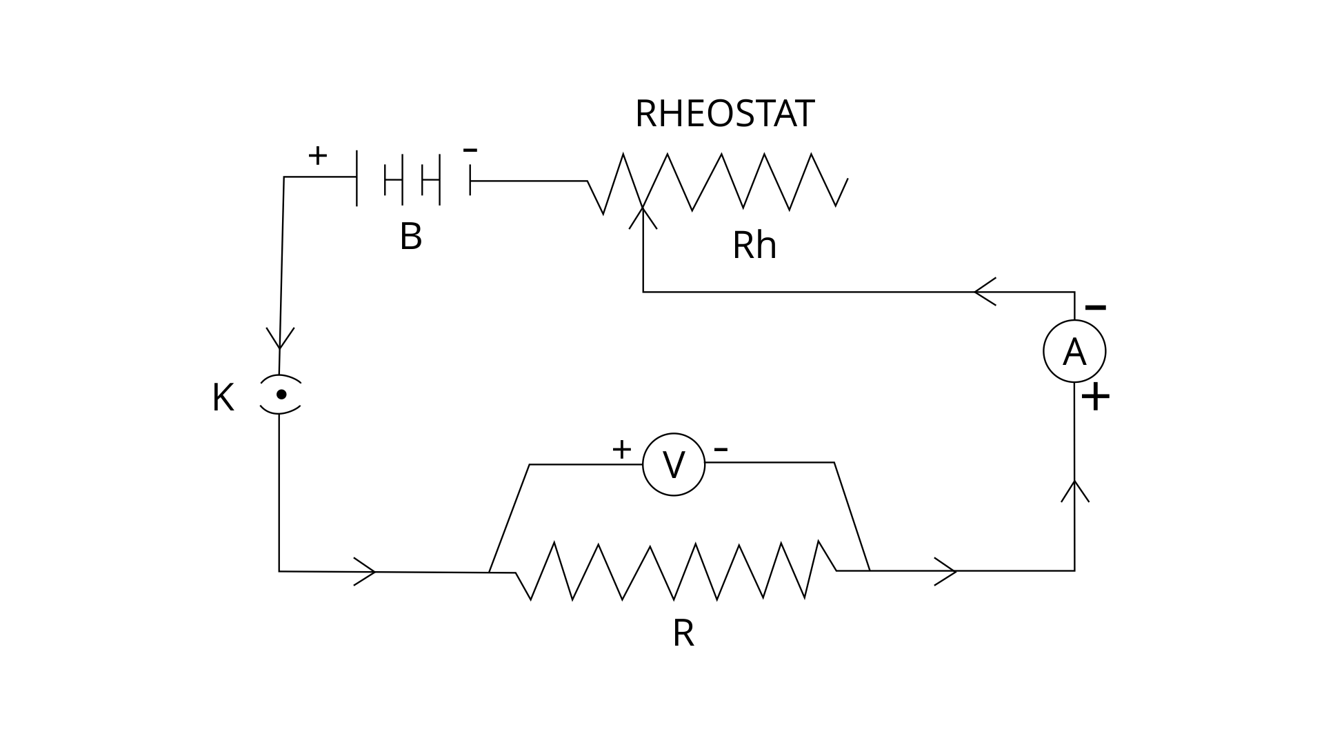
8. State Ohm’s law and draw a neat labelled circuit diagram containing a battery, a key, a voltmeter, an ammeter, a rheostat and an unknown resistance to verify it.
Ans: According to Ohm's law if the physical conditions and temperature of a conductor is kept constant then the current flowing through the conductor is directly proportional to the potential ends across the ends of conductor.
V=IR
where V is the potential difference, I is the current flowing through the conductor and R is the constant called resistance.
Diagram used for the verification of Ohm’s law
9. (a) Name and state the law which relates the potential difference and current in a conductor.
Ans: Ohm’s law relates the potential difference and current in a conductor. According to Ohm's law if the physical conditions and temperature of a conductor is kept constant then the current flowing through the conductor is directly proportional to the potential ends across the ends of conductor.
V = IR
where V is the potential difference, I is the current flowing through the conductor and R is the constant called resistance.
(b) What is the necessary condition for a conductor to obey the law named above in part (a)?
Ans: The physical conditions and temperature of the conductor should be kept constant regarding the abeyance of Ohm's law.
10. (a) Draw a V-I graph for conductor obeying Ohm’s law.
Ans:
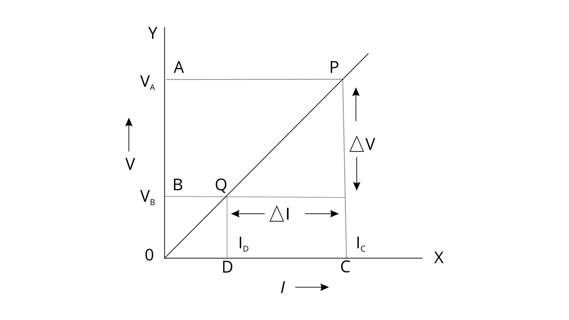
(b) What does the slope of the V-I graph for a conductor represent?
Ans: The slope of the V-I graph represents the resistance of the conductor.
Slope= Resistance=\[\frac{\Delta V}{\Delta I}\]
11. Draw an I-V graph for a linear resistor. What does its slope represent?
Ans:
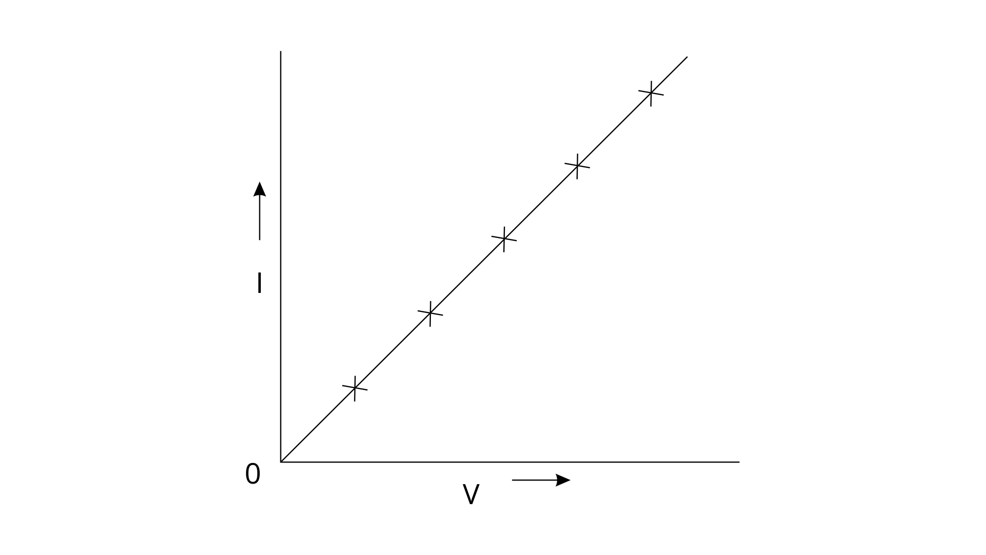
The slope of the I-V graph represents 1/Resistance of the conductor.
12. What’s an Ohmic resistor? Give one example of an ohmic resistor. Draw a graph to show its current -voltage relationship. How is the resistance of the resistor determined from the graph?
Ans: Those resistors which follow the Ohm’s law are termed as Ohmic Resistors. These include all conductors like Copper, Aluminium, Nichrome, Tungsten etc.

The resistance for these resistors is calculated with the help of slope. The slope of the straight line passing through the origin on the V-I graph gives the resistance.
Slope = Resistance =\[\frac{\Delta V}{\Delta I}\]
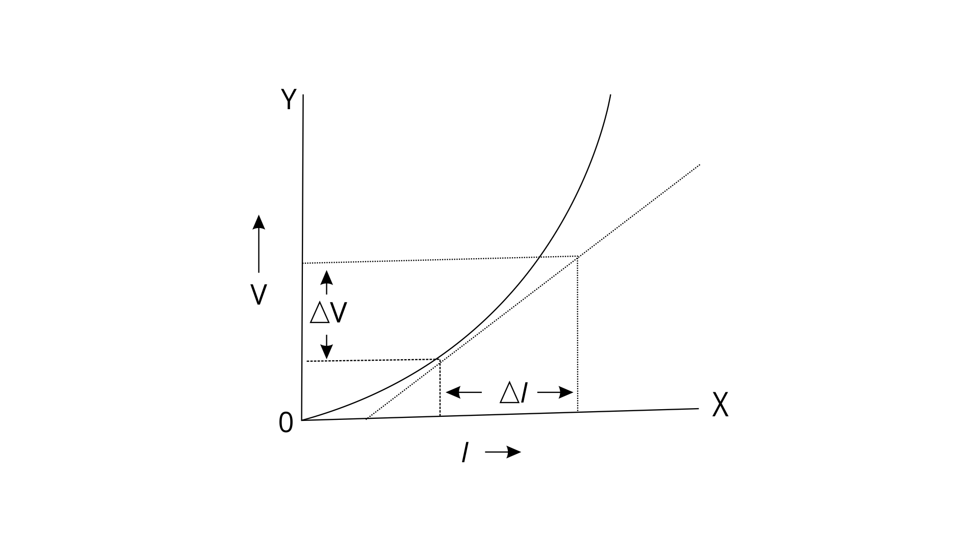
13. What are non-ohmic resistors? Give one example and draw a graph to show its current-voltage relationship.
Ans: Those resistors which don’t obey the Ohm’s law are called non-ohmic resistors. For these the slope of the V-I graph is a curve line not a straight one passing through the origin. These include solar cells, junction diode, transistor, filament of bulb and LEDs.
14. Give two differences between an Ohmic and Non-Ohmic resistor.
Ans:
15. Fig shows I-V curves for two resistors. Identify the ohmic and non ohmic resistors. Give a reason for your answer.
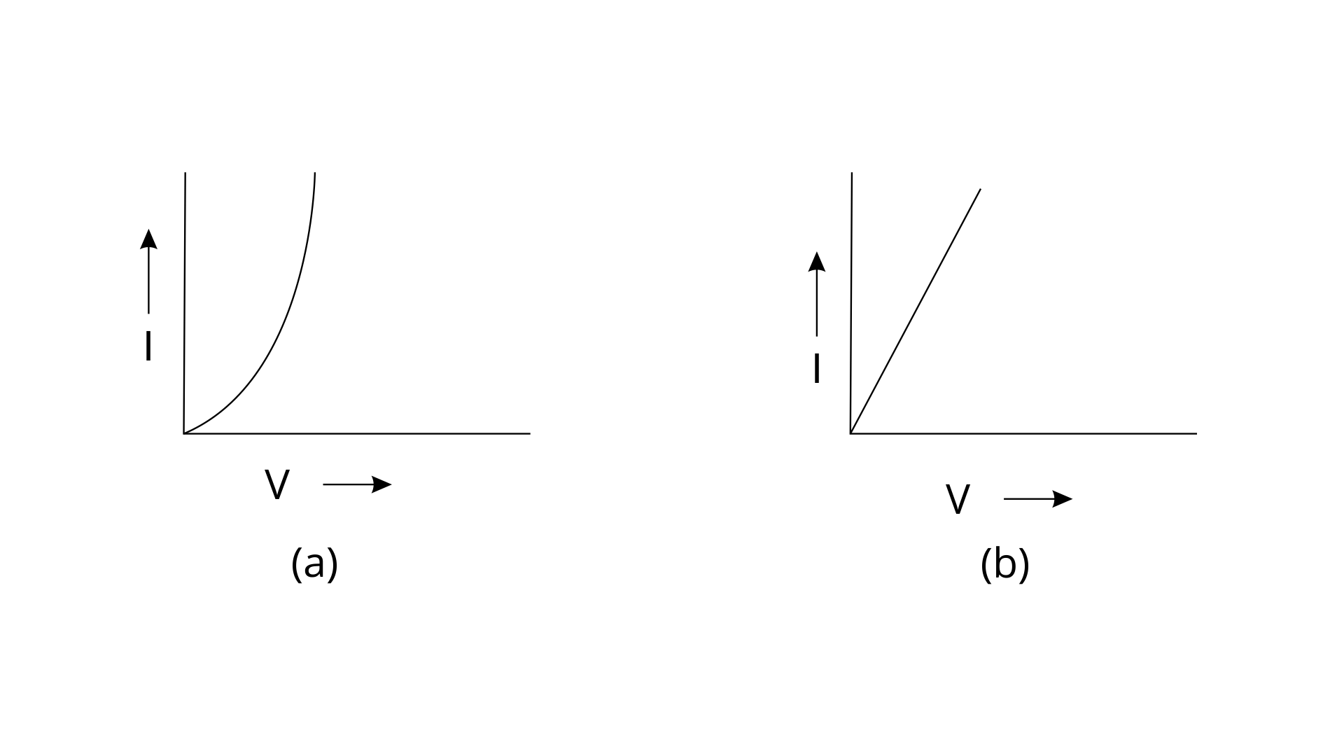
Ans: (a) is for non-ohmic resistor whereas (b) is the ohmic resistor.
Ohmic resistors are those which follow Ohm's law and the slope of the V-I graph for these is a straight line passing through the origin.
Non-Ohmic are those resistors which don’t obey Ohm's law .For these the slope of the V-I graph is a curve line not a straight one passing through the origin.
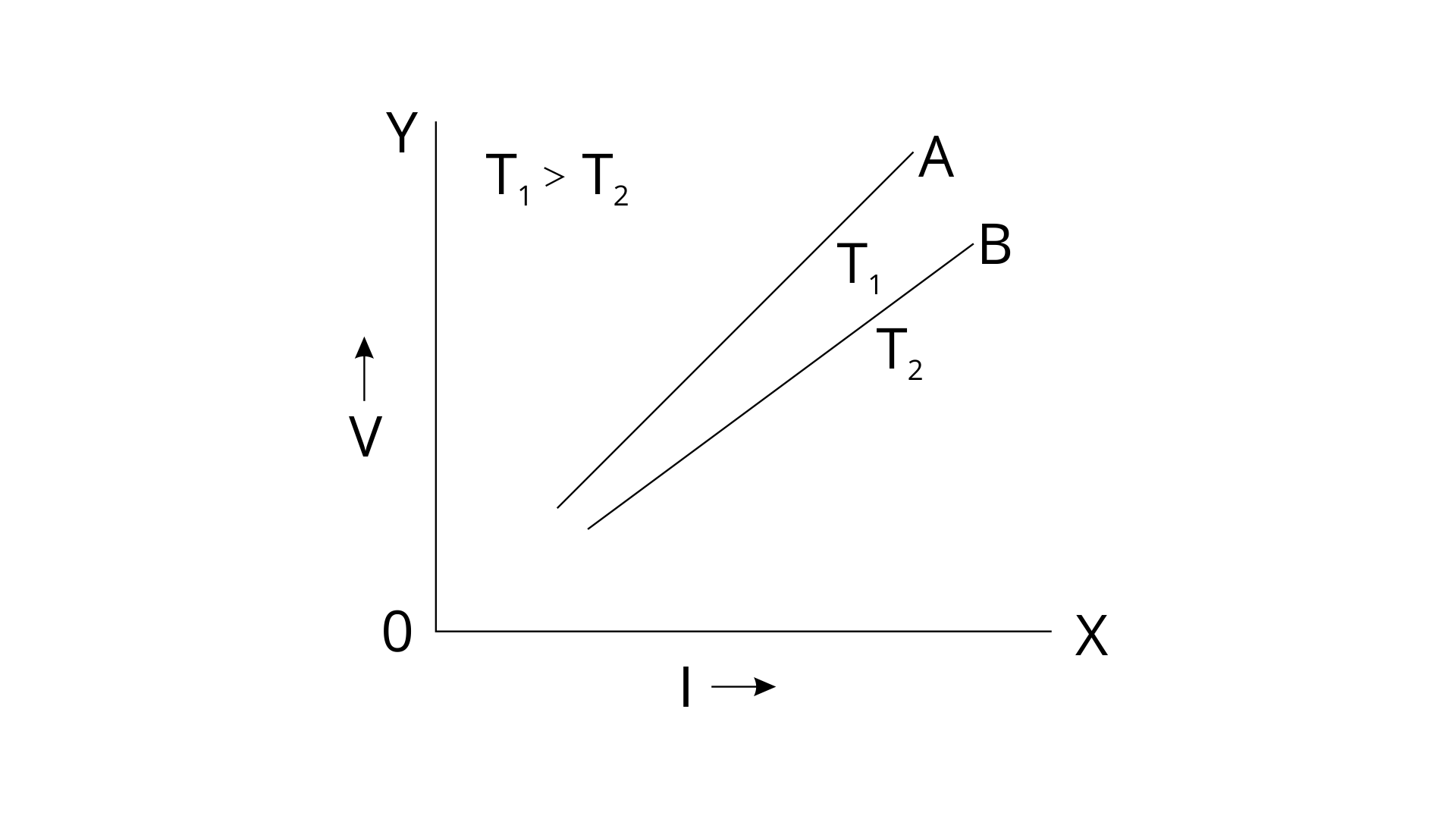
16. Draw a V-I graph for the conductor at two different temperatures. What conclusion do you draw from your graph for the variation of resistance of the conductor with temperature?
Ans: One can observe the nature of curves for both A and B. As T1>T2 the area under the curve A is more than the area under the curve B. Hence the resistance for A is more than B. This shows that resistance is directly proportional to temperature.
17. (a) How does the resistance of a wire depend on its radius? Explain your answer.
Ans: R ∝ 1/area
Resistance of wire is inversely proportional to the cross sectional area of wire, which means a thicker wire will offer less resistance as the electrons get a larger area of cross section to flow as compared to thin wire which will offer more resistance due to lesser area of cross section.
(b) Two copper wires are the same length, but one’s thicker than the other. Which will have more resistance?
Ans: The wire having a lesser area of cross-section will offer more resistance.
18. How does the resistance of the wire depend on its length? Give reason for your answer.
Ans: R ∝ length
Resistance of the wire is directly proportional to the length of the wire. A long conductor offers more collisions of free electrons with fixed positive ions leading to more resistance and less flow of current in the wire.
19. How does the resistance of a metallic wire depend on its temperature? Explain the reason.
Ans: R ∝ temperature
Resistance of a metallic wire is directly proportional to the temperature.With the increase in temperature the random motion of electrons increases resulting in more collisions of free electrons with fixed positive ions. Hence resistance increases with increase in temperature.
20. Two wires, one of copper and the other of iron, are of same length and same radius. Which one will have more resistance? Give a reason.
Ans: The resistivity or specific resistance is the materialistic property of a conductor. Iron has more value of specific resistance than that of copper hence if the length and radius of both wires are same the resistance will depend directly on the specific resistance of the material.
R ∝ resistivity
21. Name three factors on which resistance of a given wire depends and state how it is affected by the factors stated by you.
Ans: Resistance mainly depends on the length of wire, cross-sectional area of wire and the nature of material.
Resistance is in direct relation to the length of wire. (R ∝ length)
A longer wire will have more resistance than a shorter one of the same material as more collisions will take place between electrons and the fixed positive ions leading to more resistance.
esistance is inversely proportional to the cross sectional area of wire.
\[(\frac{R \propto 1}{area})\]
Which means a thicker wire will offer less resistance as the electrons get a larger area of cross section to flow as compared to thin wire which will offer more resistance due to lesser area of cross section.
Resistance is directly proportional to the nature of material or R ∝ resistivity.
The resistivity or specific resistance is the materialistic property of a conductor. Iron has more value of specific resistance than that of copper hence if the length and radius of both wires are same.
22. Define the term specific resistance and state its S.I. unit.
Ans: As per the knowledge R= ⍴l/a
Where ⍴ = resistivity or the specific resistance of the material
l = length of wire and a = cross sectional area
If the length = area = 1 then ⍴ = R which means the specific resistance is the resistance of wire when the length and cross sectional area of wire is 1unit.
The SI unit of specific resistance is Ωm.
23. Write an expression connecting the resistance of a wire and specific resistance of its material. State the meaning of the symbols used.
Ans: Formula connecting the resistance of a wire and specific resistance of its material is R= ⍴l/a, where ⍴ = resistivity or the specific resistance of the material
l = length of wire and a = cross sectional area.
24. (i) State the order of specific resistance of a metal.
Ans: For the metals the order of the specific resistance is approximately equal to 10-8 Ωm.
(ii) State the order of specific resistance of a semiconductor.
Ans: For semiconductors order of resistivity is around 10-5 Ωm
(iii) State the order of specific resistance of an insulator.
Ans: Whereas for insulators it’s 1013 Ωm.
25. (a) Name two factors on which the specific resistance of a wire depends?
Ans: (a) The specific resistance is the characteristic property of material hence it is dependent on the nature of material and also on the temperature of material.
For metals the specific resistance is directly proportional to the temperature whereas for the semiconductors the specific resistance increases with decrease in temperature.
(b) Two wires A and B are made of copper. The wire A is long and thin, while the wire B is short and thick. Which will have more specific resistance?
Ans: Both the wires A and B will have the same value of specific resistance as it’s independent of the length and cross- sectional area of wires.
26. Name a substance of which the specific resistance remains almost unchanged by the increase in temperature.
Ans: Manganin is an alloy of Copper, Nickel and Manganese and for certain alloys the specific resistance almost remains constant.
27. How does the specific resistance of a semiconductor change with the increase in temperature?
Ans: For the semiconductors the specific resistance decreases with the increase in temperature which means it’s having a negative coefficient of resistance.
28. How does (a) resistance, and (b) specific resistance of a wire depend on its (i) length, and (ii) radius?
Ans: (a) Resistance is in direct relation to the length of wire. (R∝length)
and is inversely proportional to the cross sectional area of wire (R∝1/area)
(b) Specific resistance of a wire is independent of both the length and radius as it depends only on the nature and temperature of material.
29. (a) Name the material used for making connection wires. Give a reason for your answer.
Ans: The connection wires are mainly made of Copper or Aluminium as they have very less value of specific resistance. Because of the low value of specific resistance the current almost remains constant and hence the dissipation in heat is prevented.
(b) Why should a connection wire be thick?
Ans: The connection wires should be made thick as a wire will be more will be the area for electrons to face the collisions with the fixed positive ions, hence the resistance will be less leading to less heat losses.
\[(\frac{R \propto 1}{area})\]
30. Name a material which is used for making a standard resistor. Give a reason for your answer.
Ans: In order to make a standard resistor the material should have a high value of resistance and their values should not change often with temperature. So, Manganin is suitable for making standard resistors.
31. Name the material used for making a fuse wire. Give a reason.
Ans: Alloys of copper and tin are generally used for making the fuse wire. Because of the low value of melting point and high value of specific resistance they are more suitable for the flow of current upto the safe limit.
32. (i) Name the material used for filament of an electric bulb.
Ans: Tungsten is used mainly for the filament of the electric bulb because of the high value of melting point.
(ii) Name the material used for the heating element of a room heater.
Ans: Nichrome is used as the heating element of a room heater. The specific resistance of nichrome is high and it also increases with increase in temperature.
33. What is a superconductor? Give one example of it.
Ans: Superconductors are those substances which have zero resistance at a very low temperature. As the resistance of these materials is zero they will have infinite conductance. Example: Lead below 7.25K.
34. A substance has zero resistance below 1K. What is such a substance called?
Ans: This substance is called Superconductor. Superconductors are those substances which have zero resistance at a very low temperature.
Multiple Choice Type
1. Which of the following is an ohmic resistance?
(a) LED
(b) junction diode
(c) filament of a bulb
(d) nichrome wire
Ans: Correct option (d) Nichrome wire
Explanation:- LED, junction diode and filament of bulb are the examples of non ohmic devices whereas nichrome wire is an ohmic resistance device.
2. For which of the following substances, resistance decreases with the increase in temperature?
(a) Copper
(b) mercury
(c) Carbon
(d) platinum
Ans: Correct option (c) carbon
Explanation: Copper, mercury, platinum are the examples of metals and for those the resistance always increases with the increase in temperature. Hence carbon is a semiconductor material and for these the resistance decreases with the increase in temperature.
Numericals
1. In a conductor 6.25 × 10¹⁶ electrons flow from its end A to B in 2s. Find the current flowing through the conductor. (e = 1.6 × 10⁻¹⁹ C)
Ans:No. of electrons flowing(n) = 6.25 × 10¹⁶
Charge on each electron =1.6 × 10⁻¹⁹ C
Hence current (i) = ne/t
Where n = no. of electrons flowing through the conductor.
e = electronic charge
t = time for which the electrons flow
i = 6.25 × 1016 × 1.6 × 10-19 /2
i = 5 × 10⁻³ A = 5mA
The current flowing through the end B to A is 5mA.
2. A current of 1.6mA flows through a conductor. If charge on an electron is -1.6 × 10⁻¹⁹ C, find the number of electrons that will pass each second through the cross section of that conductor.
Ans: Current (I) = 1.6mA = 1.6 × 10⁻³A
Charge on each electron = -1.6 × 10⁻¹⁹ C
No. of electrons = ?
Current (I) = ne/t
1.6 × 10-3 = 1.6 × 10⁻¹⁹ × n (taking the magnitude of charge only)
n= 1.6 × 10⁻³/1.6 × 10-19
n=1016 therefore no of electrons flowing through the conductor is 1016.
3. Find the potential difference required to flow a current of 200mA in a wire of resistance 20Ω.
Ans: Current (I) = 200mA = 200 × 10-3 A = 0.2A
Resistance (R) = 20Ω.
According to Ohm’s law V = IR
Hence V= 0.2 × 20 =4
Therefore the potential difference required to flow the current is 4V
4. An electric bulb draws 1.2A current at 6.0V. Find the resistance of the filament while glowing.
Ans: Current(I) = 1.2.A
Potential difference (V)=6V
Acc. to Ohm’s law V=IR
Hence R =V/I = 6/1.2 = 60/12 = 5Ω
Hence the resistance of the filament while glowing = 5Ω
5. A car connected to a 12 volt battery draws 2A current when glowing.What is the resistance of the filament of the bulb? Will the resistance be more,same or less when the bulb is not glowing?
Ans:-Potential difference across car =12V
Current (I)=2A
According to Ohm’s law V=IR
Hence R=V/I = 12/2 =6Ω
Therefore the resistance of filament of the bulb is 6Ω.
The resistance will be more if the bulb is not glowing as there is no current flowing through the bulb at that time.
6. Calculate the current flowing through the wire of resistance 5Ω connected to a battery of potential difference 3V.
Ans: Potential difference across battery =3V
Resistance(R) = 5Ω
According to Ohm’s law V=IR
Hence I = V/R = 3/5 = 0.6A
The current flowing through the battery is 0.6A
7. In an experiment of verification of Ohm’s law, following observations are obtained.
Draw a V-I graph and use this graph to find:
(a) the potential difference V when the current I is 0.5A.
Ans:
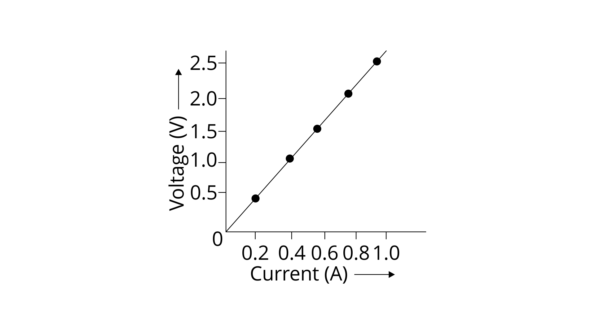
When the current is 0.5A the potential difference = 1.25V
(b) the current I when the potential difference V is 0.75V
Ans: when the potential difference is 0.75 V the current is 0.3A
(c) the resistance in the circuit
Ans: Resistance = slope of V-I graph = 1.0-0.5/0.4-0.2 = 0.5/0.2 = 2.5Ω
8. Two wires of the same material and same length have radii 1mm and 2mm respectively. Compare
(i) their resistances
Ans: radii(r1) = 1 mm = 1 × 10⁻³m
radii(r2) = 2mm =2 × 10⁻³m
Area(A1) = π(r1)2
Similarly Area (A2) = π(r2)2
As (R∝1/area)
so R1/R2= A2/A1
= π(r2)2/ π(r1)2
= π × 4 × 10 – 6/ π × 1 × 10-6 = 4:1
Hence, the resistances are in the ratio 4:1.
(ii) their specific resistance
Ans: Since the nature of material is the same, the specific resistances will also be the same as it’s independent of length and radius. So the ratio will be 1:1.
9. A given wire of resistance 1Ω is stretched to double its length. What will be its new resistance?
Ans: Resistance =1Ω
Original length = l1
According to the ques it’s said that the new length l2= double of original length = 2l1………..(i)
The volume of wire will always remains constant hence A1l1=A2l2
So A1 l1 = A2 2 l1
Or A2 = A1/2……………..(ii)
As we know R1 = ₰l1/A1 and R2 = ₰l2/A2,
R1/R2 = l1A2/l2A1……………….(iii)
Substituting (i) and (ii) in (iii)
R1/R2 = 1/4 and since R1 = 1Ω the new resistance will be R2= 4Ω
10. A wire of resistance 3Ω and length 10cm is stretched to length 30cm. Assuming that it has a uniform cross section, what will be its new resistance?
Ans: Resistance =3Ω
Original length = 10cm
According to the question it’s said that the new length l2 = 30cm
And the area of cross section is uniform which means (R∝length)2
Hence R2/R1 =(l2/l1)2
R2/R1=9 and since R1=3Ω the new resistance will be R2= 9Ω
11. A wire of resistance 9Ω having length 30 cm is tripled on itself. What is the new resistance?
Ans: Resistance = 9Ω
Original length = l1
According to the ques it’s said that the new length l2= tripled on itself = l1/3 = 30/3 =10cm………..(i)
The volume of wire will always remain constant hence A1l1=A2l2
So A1 × 30 = A2 × 10
Or A2=3A1……………..(ii)
As we know R1=₰l1/A1 and R2=₰l2/A2,
R1/R2= l1A2/l2A1……………….(iii)
Substituting (i) and (ii) in (iii)
R1/R2=9 and since R1=9Ω the new resistance will be R2= 1Ω
12. What length of copper wire of specific resistance 1.7 × 10⁻⁸ Ωm and radius 1mm is required so that its resistance is 1Ω?
Ans: Resistance of wire = 1Ω
Radius of wire = 1mm = 10-3 m hence Area = π × 10-6m2.
Specific resistance (₰)=1.7 × 10⁻⁸Ωm
As we know R=₰l/A
So the length of wire l=RA/₰
= 1× π × 10-6 / 1.7 × 10-8 = 1.847 × 10²m = 184.7m
13. The filament of a bulb takes a current 100mA when the potential difference across it is 0.2V. When the potential difference across it becomes 1.0V, the current becomes 400mA. Calculate the resistance of the filament in each case and account for the difference.
Ans: Potential difference across bulb = 0.2V
Current (I) = 100mA = 0.1A
According to Ohm’s law V=IR
Or R =V/I = 0.2/0.1 =2Ω
In the second case when the current becomes 400mA = 0.4A
Potential difference =1V
Again by Ohm’s law V2=I2R2
Or R2=V2/I2 = 1/0.4 = 2.5Ω
Hence one can say that when the potential difference is increased the resistance also increases.
Exercise (8B)
1. Explain the meaning of the term e.m.f., terminal voltage, and internal resistance of a cell.
Ans:
e.m.f.: The electro-motive force (e.m.f.) is defined as the maximum potential difference that can be applied in the circuit within which no current is flowing in it.
Terminal Voltage: The potential difference between the electrodes of the cell when current is drawn from a cell is called its terminal voltage or in other words the potential difference across the points through the resistance R is called terminal voltage.
Internal Resistance: The internal resistance of the cell is defined as the resistance offered by the electrolyte inside the cell when current passes through it.
2. State two differences between the e.m.f. and terminal voltage of a cell
Ans:
3. Name two factors on which the internal resistance of a cell depends and state how it depends on the factors stated by you.
Ans: The factors on which internal resistance of a cell depends are given below:
(i) The surface area of the electrodes: if we take Larger the surface area of the electrodes of the cell then its internal resistance would be less.
(ii) The distance between the electrodes: if we take a cell which has greater the between the electrodes of the cell then it has more internal resistance.
4. A cell of e.m.f. ε and internal resistance r is used to send current to an external resistance R. Write expression for
(a) the total resistance of circuit,
Ans: Total resistance = R + r
(b) the current drawn from the cell,
Ans: Current drawn from the circuit:
As we know that,
ε = V + v
ε = IR + Ir
ε = I(R+r)
I = ε/ (R + r)
(c) the p.d. across the cell, and
Ans: p.d. across the cell: (𝜀R)/(𝑅+𝑟)
(d) the voltage drops inside the cell.
Ans: Voltage drop inside the cell: (𝜀r)/(𝑅+𝑟)
5. A cell is used to send current to an external circuit.
(a) How does the voltage across its terminals compare with its e.m.f.?
Ans: A cell is used to send current to an external circuit the voltage across its Terminal (terminal voltage) is less than the emf.
(b) Under what condition is the e.m.f. of the cell equal to its terminal voltage?
Ans: When no current is drawn in the circuit then the emf of the cell is equal to the terminal voltage.
6. Explain why the p.d. across the terminals of a cell more in an open circuit and reduced in a closed circuit.
Ans: When an electric cell is in a closed circuit, the current flows in a circuit. There is a decrease in potential through all internal cell resistance of the cell. Therefore, p.d. across the terminals in a closed circuit is less than p.d. across the terminals in an open circuit. And this decreased potential is equal to the potential drop across the internal resistance of the cell.
7. Write the expressions for the equivalent resistance R of three resistors R1 R2 and R3 join in (a) series.
Ans:
(a) Total Resistance in series:
R = R1 + R2 + R3
(b) in parallel.
Ans: Total Resistance in parallel:
1/R = 1/R1 + 1/R2 +1/R3
8. How would you connect two resistors in series? Draw a diagram. Calculate the total equivalent resistance.
Ans: Connections of two resistors in series –
If current I is drawn from the battery. We know that in series connections, the current through all resistors will be the same as I.
On applying Ohm's law to the two resistors separately, we further have
V1 = I R1
V2 = I R2
V= V1 + V2
IR = I R1+ I R2
R = R1+ R2
Total Resistance in series R = R1+ R2
That is the sum of all resistances connected in series.
9. Show by diagram how two resistors R1 and R2 are joined in parallel. Obtain an expression for the total resistance of the combination.
Ans: Two resistors R1 and R2 are joined in parallel shown in figure
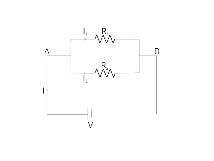
We know that in parallel combinations the potential across the resistors are the same , which is V and current is divided through all the resistors.
On applying Ohm's law to the two resistors separately, we further
Have
I1 = V / R1
I2 = V / R2
I = I1 + I2
V / R = V / R1+ V / R2
Then the total Resistance in parallel:
1/R = 1/R1 + 1/R2
10. State how are the two resistors joined with a battery in each of the following cases when:
(a) same current flows in each resistor.
Ans: Two resistors joined in series with a battery, then the same current flows in each resistor.
(b) potential difference is the same across each resistor.
Ans: Two resistors joined in parallel with a battery, then potential difference is the same across each resistor.
(c) equivalent resistance is less than either of the two resistors and
Ans: Two resistors joined in parallel with a battery then equivalent resistance is less than either of the two resistors
(d) equivalent resistance is more than either of the two resistances.
Ans: Two resistors joined in series with a battery then equivalent resistance is more than either of the two resistances.
11. The V-I graph for a series combination and for a parallel combination of two resistors is shown in fig. 8.40. Which of the following two, A or B, represent the parallel combination? Give a reason for your answer.

Ans: As we know that the slope of the V-I graph gives resistance. From the diagram straight line A is less steeper than line B. It means slope of line A is less than line B. Therefore line A represents small resistance and line B represents more resistance. And we also know that the equivalent resistance for two resistances in series connection is more than in parallel connections .So straight line A represents the parallel combination.
Multiple Choice Type
1. In series combination of resistances:
(a) p.d. is the same across each resistance.
(b) total resistance is reduced
(c) current is same in each resistance
(d) all above are true.
Ans: Option (c) is the correct answer.
We know that in series combination the current is the same in each resistance that is connected in the circuit.
2. In parallel combination of resistances:
(a) p.d. is the same across each resistance.
(b) total resistance is increased
(c) current is same in each resistance
(d) all above are true.
Ans: Option (a) is the correct answer.
We know that in parallel combinations of resistances the potential difference is the same across each resistance that is connected in the circuit.
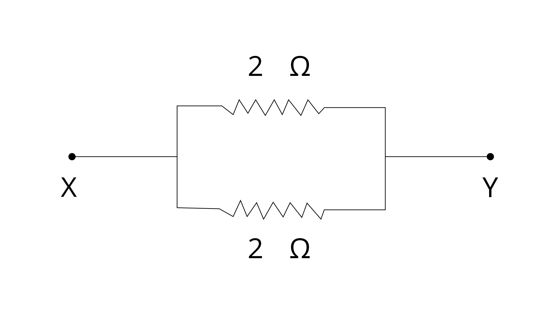
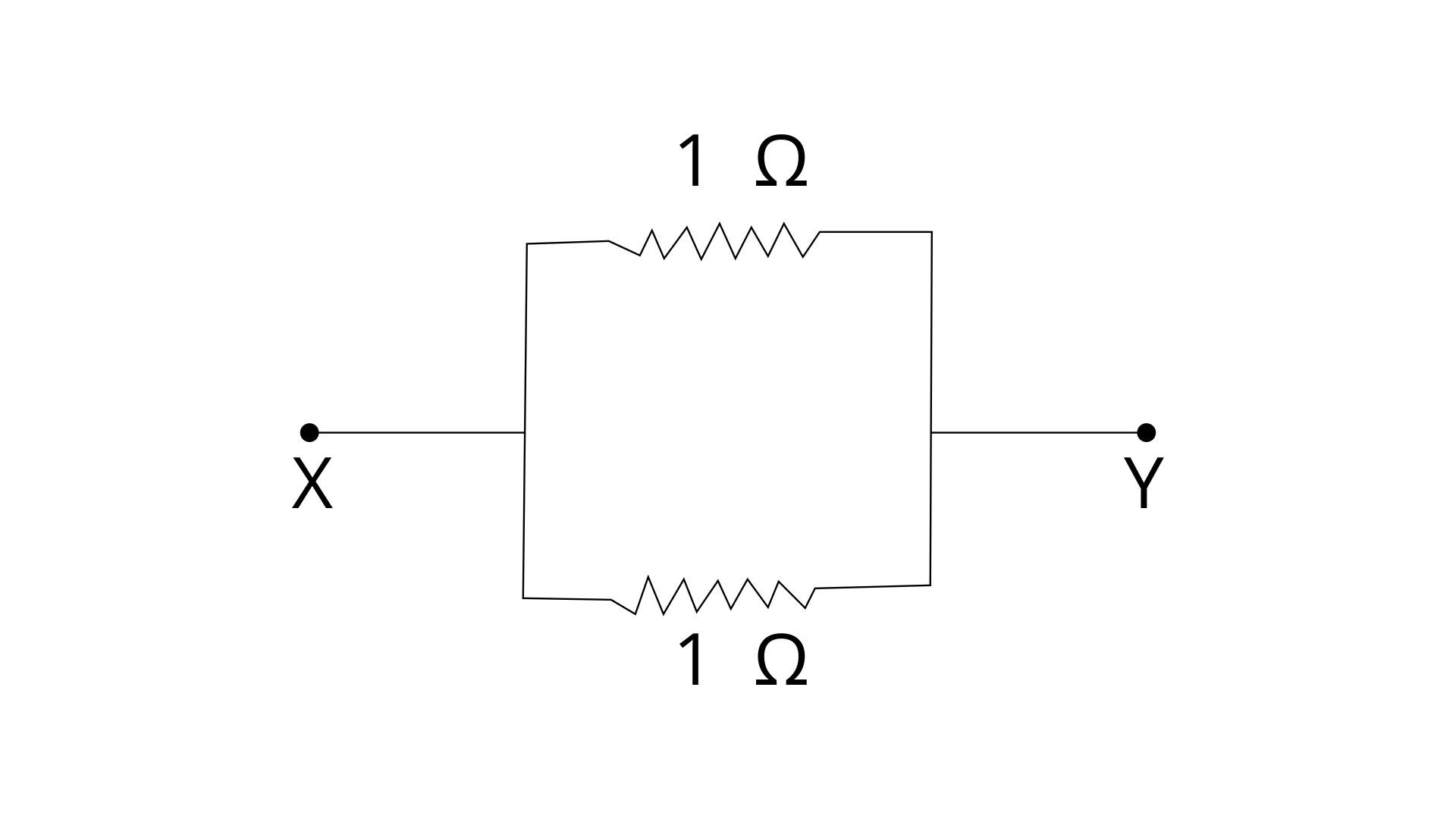
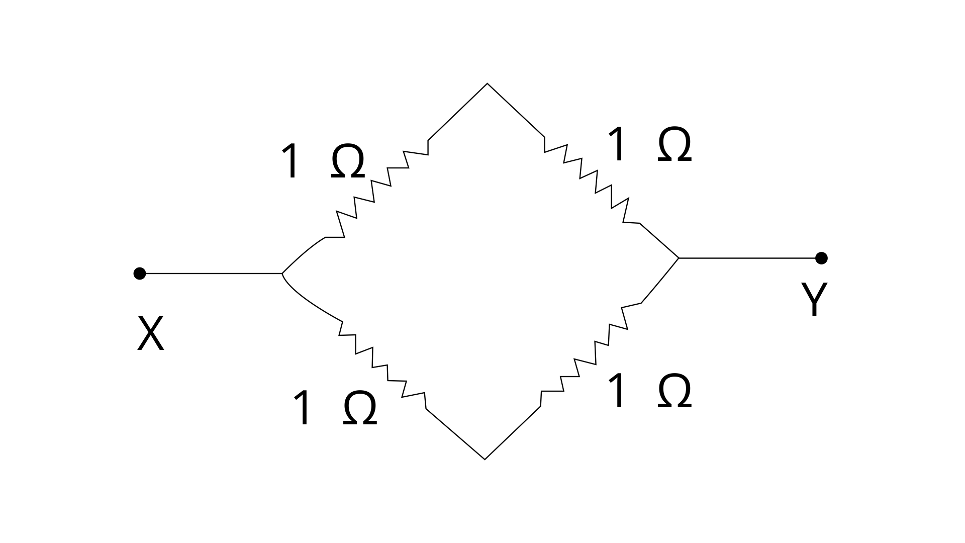
3. Which of the following combinations have the same equivalent resistance between X and Y?
(a)
(b)
(c)
(d)
Ans:
Option (a) and (d) are correct options.
In fig (a), the resistors are connected in parallel
Between X and Y.
Let R be the equivalent resistance.
the total Resistance in parallel:
1/R = 1/R1 + 1/R2
1/R = ½ + ½ = 1
R = 1 Ω ………………….(i)
In fig (d) a series combination of two 1Ω resistors is in parallel with another series combination of two 1Ω resistors
Series resistance of two 1 Ohm resistors,
R = 1 + 1 = 2 Ω
Thus, we can say that across X and Y, two 2Ω resistors
are connected in parallel
Let R’ be the net resistance across X and Y then
1/R’ = ½ + ½
R’ = 1 Ω …………………… (ii)
From (i) and (ii), it is clear that (a) and (d) have the same equivalent resistance between X and Y.
Numericals
1. The diagram in Fig. 8.40 shows a cell of e.m.f. ε = 2 volt and internal resistance r = 1 ohm to an external resistance R = 4 ohm. The ammeter A measures the current in the circuit and the voltmeter V measures the terminal voltage across the cell. What will be the readings of the ammeter and voltmeter when (i) the key K is open,
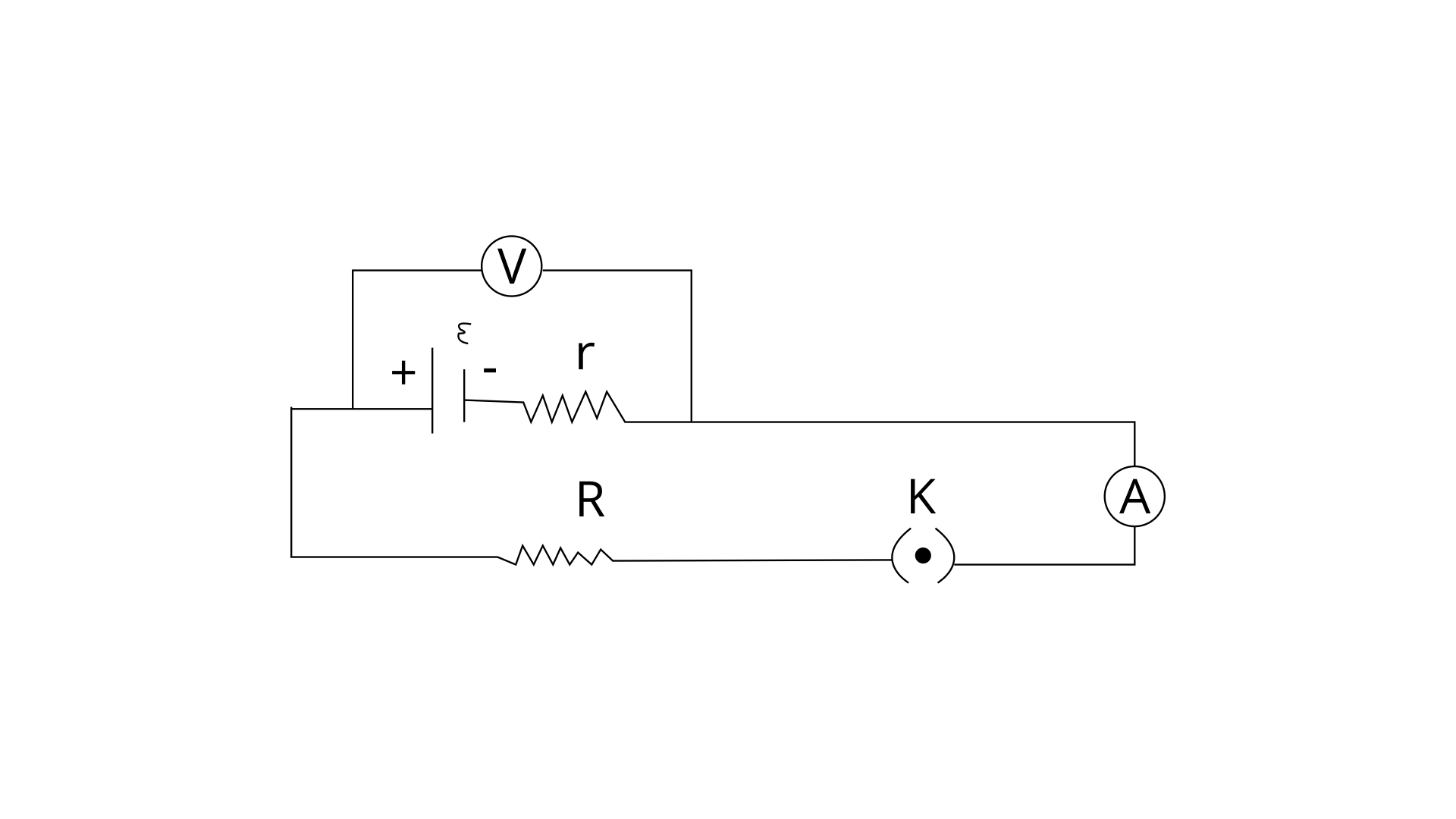
Ans: (i) when the key K is open then there is no current so Ammeter reading would be zero
Ammeter reading = 0
Voltage V = ϵ − Ir
V = 2 – (0 × 1) = 2 volt
So voltmeter reading = 2 volt
(ii) When the key K is closed.
Ans: when the key K is closed then Ammeter reading:
\[I =\frac{\varepsilon}{(R+r)}\]
I = 2 / (4+1) = 2 / 5 = 0.4 A
Ammeter reading = 0.4 amp
Voltage reading:
Voltage V = ϵ - Ir
V = 2 - 0.4 x 1 = 2 - 0.4 = 1.6 V
Voltage reading = 1.6 V
2. A battery of e.m.f. 3.0 V supplies current through a circuit in which the resistance can be changed. A high resistance voltmeter is connected across the battery. When the current is 1.5 A, the voltmeter reads 2.7 V. Find the internal resistance of the battery.
Ans: Given e.m.f. = ε = 3 volt
I = 1.5 A
V = 2.7 V
By formula V = ε − Ir
Here r is the internal resistance of the cell or battery.
r = (ε - V) / I
r = (3 – 2.7) / 1.5 = 0.2 ohm
3. A cell of e.m.f. 1.8 V and internal resistance 2 Ω is connected in series with an ammeter of resistance 0.7 Ω and a resistor of 4.5 Ω as shown in Fig.
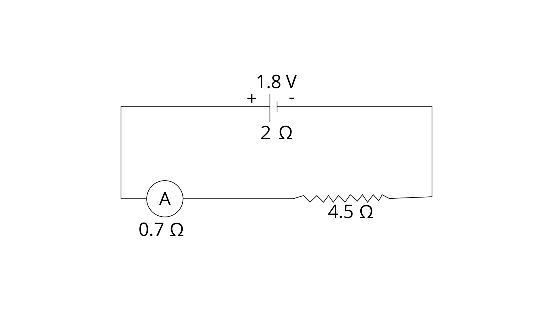
(a) What would be the reading of the ammeter?
Ans: Given emf = ε = 1.8 V
Total Resistance = R = 2 + 4.5 + 0.7 = 7.2 W
Current = I = ?
I = ε / R (total resistance)
I = 1.8 / 7.2 = 0.25 A
Reading of the ammeter Current = 0.25 A
Now, total resistance excluding internal resistance = 4.5 + 0.7 = 5.2 ohm
(b) What is the potential difference across the terminals of the cell ?
Ans: V = IR = 0.25 x 5.2 = 1.3 V
Potential difference across the terminals of the cell is 1.3 V.
4. A music system draws a current of 400 mA when connected to a 12V battery.
(a) What is the resistance of the music system?
Ans: Given: current = I = 400mA = 0.4A,
V=12V
By ohm’s law Resistance of the music system =
R = V/I
R = 12 /0.4
R = 30 Ω
(b) The music system is left playing for several hours and finally the battery voltage drops and the music system stops playing when the current drops to 320mA. At which battery voltage does the music system stop playing?
Ans: Given: I = 320 mA = 0.32A
Resistance of music system = 30Ω
According to Ohm's law,
V= IR = 0.32 ✕ 30 = 9.60V
The music system stops playing at 9.60 Volt.
5. A cell of e.m.f. ε and internal resistance r sends a current 1.0 A when it is connected to an external resistance 1.9 Ω. But it sends current 0.5 A when it is connected to an external resistance of 3.9 Ω. Calculate the values of ε and r.
Ans: In first case
I = 1 A, R = 1.9 Ω
ε = I(R + r) = 1(1.9+r)
ε = 1.9 + r------------(1)
In second case
I = 0.5 A, R = 3.9 Ω
ε = I(R + r) = 0.5 (3.9 + r)
ε = 1.95 + 0.5r ----------------(2)
From eq. (1) and (2),
1.9 + r = 1.95 + 0.5r
r = 0.05/0.5 = 0.1 Ω
So internal resistance of the cell is o.1 Ω
Substituting value of r
ε = I(R + r) = 1( 1.9 + r) = 1.9 + 0.1 = 2 V
6. Two resistors having resistance 4 Ω and 6 Ωare connected in parallel. Find their equivalent resistance.
Ans: Let R be their equivalent resistance of the 4Ω and 6Ω resistors connected in parallel. Then by formula
1/R = 1/R1 + 1/R2
1/R = ¼ + ⅙ = 10/24
R = 24/10 = 2.4 Ω
7. Four resistors each of resistance 2 Ω are connected in parallel. What is the effective resistance?
Ans: Given R1 = 2 Ω
R2 = 2 Ω
R3 = 2 Ω
R4 = 2 Ω
Now by formula of equivalent resistance in parallel combination
1/R = 1/R1 + 1/R2 + 1/R3 + 1/R4
1/R = ½ + ½ + ½ + ½
1/R = 2
R = ½ = 0.5 Ω
8. You have three resistors of values 2Ω , 3Ω and 5Ω . How will you join them so that the total resistance is less than 1 Ω ? Draw a diagram and find the total resistance.
Ans: The three resistors (2Ω , 3Ω and 5Ω) should be connected in parallel combination to get a total resistance less than 1Ω
Let R be the total resistance then by formula
1/R = 1/R1 + 1/R2 + 1/R3
1/R = ½ + ⅓ + ⅕
1/R = 31/30
R = 30/31 = 0.97 ohm
9. Three resistance each of 2 Ω are connected together so that their total resistance is 3 Ω. Draw a diagram to show this arrangement and check it by calculation.
Ans: A parallel combination of two resistors, in series with one resistor.
Given R1 = 2 Ω
R2 = 2 Ω
R3 = 2 Ω
Let R’ be the total resistance then by formula
1/R’ = 1/R1 + 1/R2
1/R’ = ½ + ½ = 1
R’= 1 Ω
Now this resistance is in series with 2 ohm
R = 1 + R3
R = 1 +2 = 3 Ω
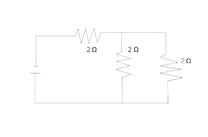
10. Calculate the equivalent resistance between the points A and B in Fig. 8.44 if each resistance is 2.0 Ω.
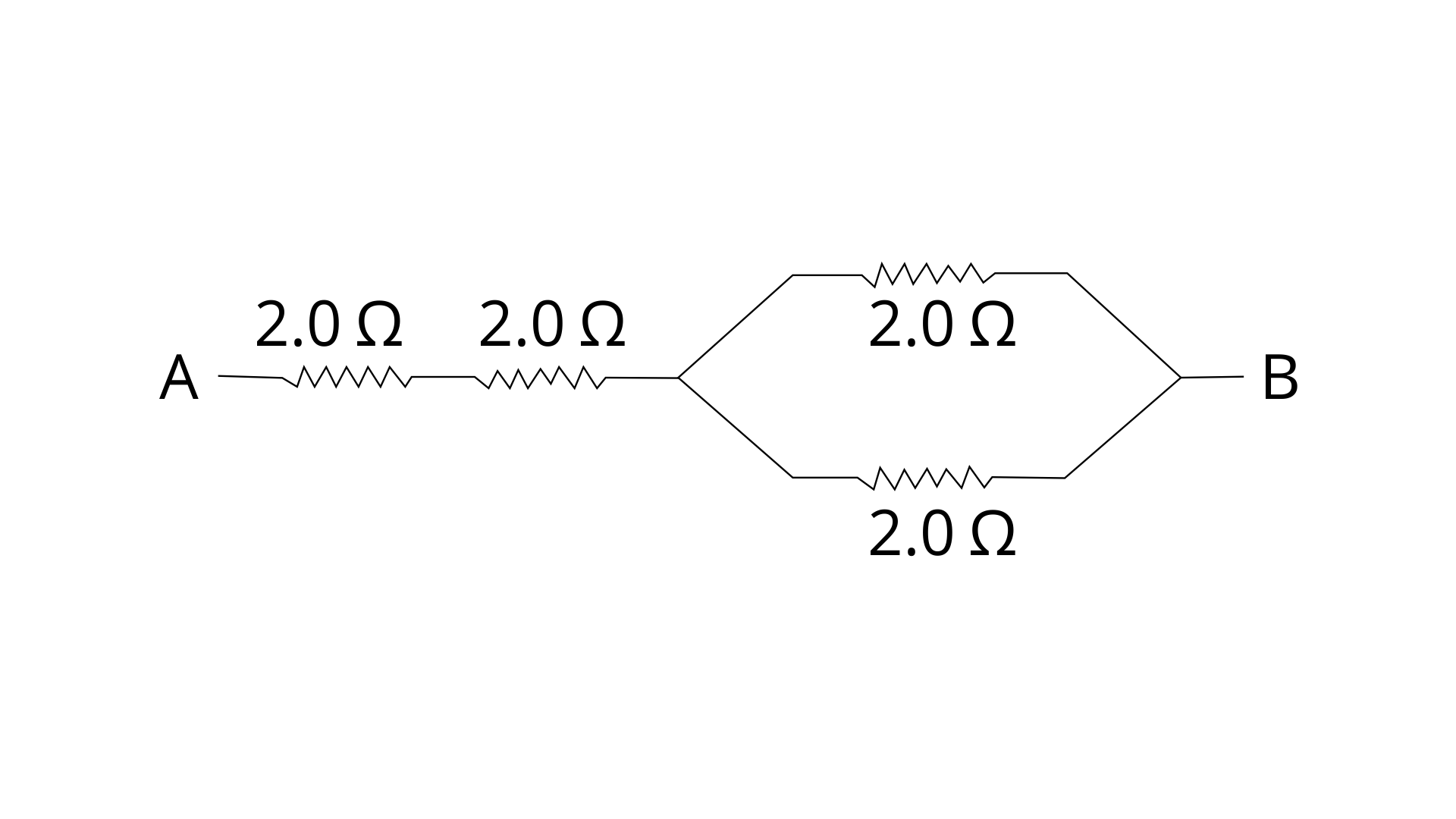
Ans: Given R1 = R2 = R3 = R4 = 2 Ω
R’ = R1+ R2
R’ = 2 + 2 = 4 Ω
1/R’’ = 1/R3 + 1/R4
1/R’’ = ½ + ½ = 1
R’’= 1 Ω
Now equivalent resistance R = R’ +R’’
R = 4 + 1 = 5 Ω
Equivalent resistance between the points A and B is 5 ohm
11. A combination consists of three resistors in series. Four similar sets are connected in parallel. If the resistance of each resistor is 2 ohm, find the resistance of the combination.
Ans: Given resistance of each resistor r = r1 = r2 = r3 = 2
Resistance of each set:
R1 = 2 + 2 + 2 = 6 Ω
R2 = 2 + 2 + 2 = 6 Ω
R3 = 2 + 2 + 2 = 6 Ω
R4 = 2 + 2 + 2 = 6 Ω
Now these resistances are arranged in parallel:
1/R = 1/R1 + 1/R2 + 1/R3+ 1/R4
1/R = ⅙ + ⅙ + ⅙ + ⅙
1/R = 4/6
R = 6/4 = 1.5 Ω
Resistance of the combination = R = 1.5 ohm
12. In the circuit shown below in figure, calculate the value of x if the equivalent resistance between the points A and B is 4 Ω
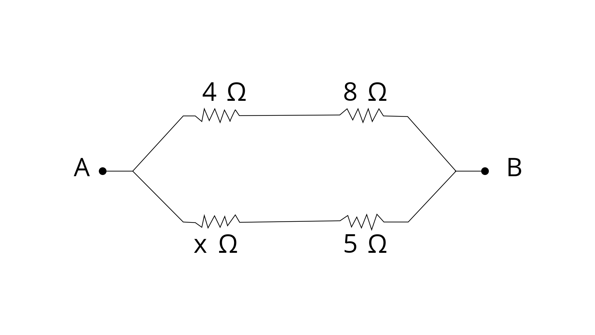
Ans:
Given R1 = 4 Ω
R2 = 8 Ω
R3 = x Ω
R4 = 5 Ω
Equivalent resistance = R = 4 Ω
R’ = R1+ R2
R’ = 4 + 8 = 12 Ω
R’’ = R3+ R4
R’’ = x + 5 = (x+5) Ω
Now R’ and R’’ are in parallel combination then by formula -
1/R = 1/R’ + 1/R’’
¼ = 1/12 + 1/(x + 5)
⅙ = 1/(x + 5)
X + 5 = 6
X = 6 - 5 = 1 ohm
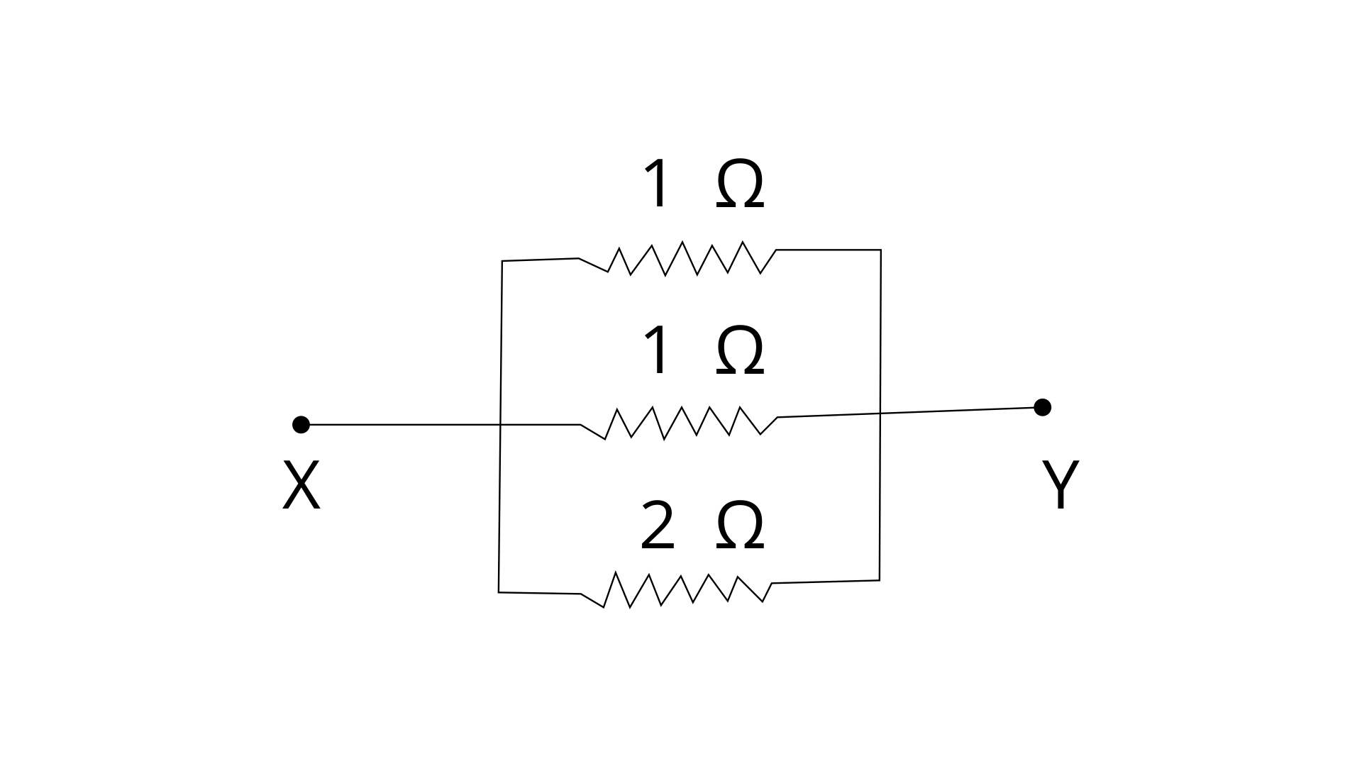
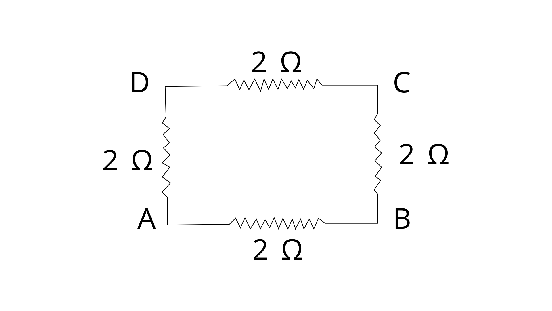
13. Calculate the effective resistance between the points A and B in the circuit shown in fig.
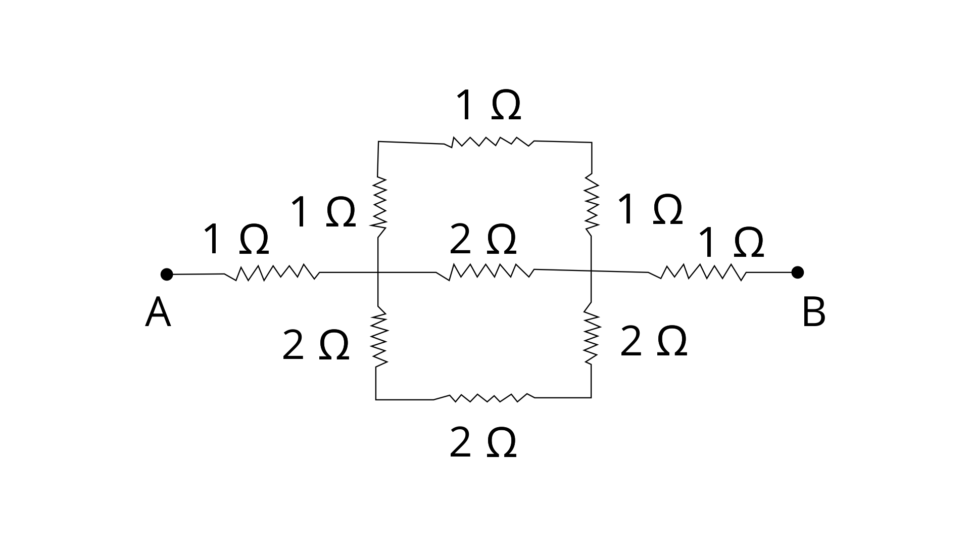
Ans: In the below figure,
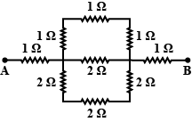
Resistance between XY in upper arm of = (1 + 1 + 1) = 3 Ω (three resistance of 1 ohm are in series)
Resistance between XY in middle arm = 2 Ω
Resistance between XY in below arm = 2 + 2+ 2 + = 6 Ω (three resistance of 2 ohm are in series)
Let R be the net resistance between points X and Y Then,
1/R = 1/2 + 1/3 + 1/6 = (3 + 2 + 1)/6
R = 6 /6 = 1 Ω
Thus, now we can say that between points A and B, Three 1 Ω resistors are connected in series.
Let RAB be the net resistance between points A and B.
Then, RAB = (1 + 1 + 1) = 3 Ω
14. A uniform wire of resistance of 27 Ω is divided into three equal pieces and then they are joined in parallel. Find the equivalent resistance of the parallel combination.
Ans: It is given that a uniform Wire cut into three pieces. We know that the resistance of a wire is directly proportional to the length of the wire.
So new resistance will be = 27/3 = 9 Ω
Now three resistance connected in parallel
1/R = 1/R1 + 1/R2 + 1/R3
1/R = 1/9 + 1/9 + 1/9
1/R = 3/9 = 1/3
R = 3 Ω
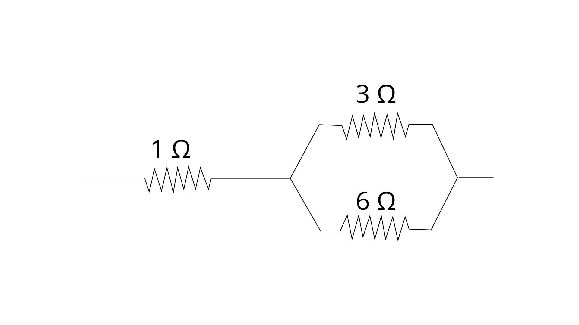
15. A circuit consists of a resistance of 1 ohm in series with a parallel arrangement of resistors of 6 ohm and 3 ohm. Calculate the total resistance of the circuit. Draw diagram of the arrangement.
Ans: Parallel arrangement of resistors of 6 ohm and 3 ohm gives the resistance by formula -
1/R = 1/R1 + 1/R2
1/R = ⅙ + ⅓ = ½
R = 2 Ω
Now this 2 ohm is in series connection with 1 ohm then total resistance of the circuit is
Req = R + 1 = 2 + 1 = 3 Ω
Diagram of the given arrangement is shown below,
16. Calculate the effective resistance between the points A and B in the network shown below in figure.
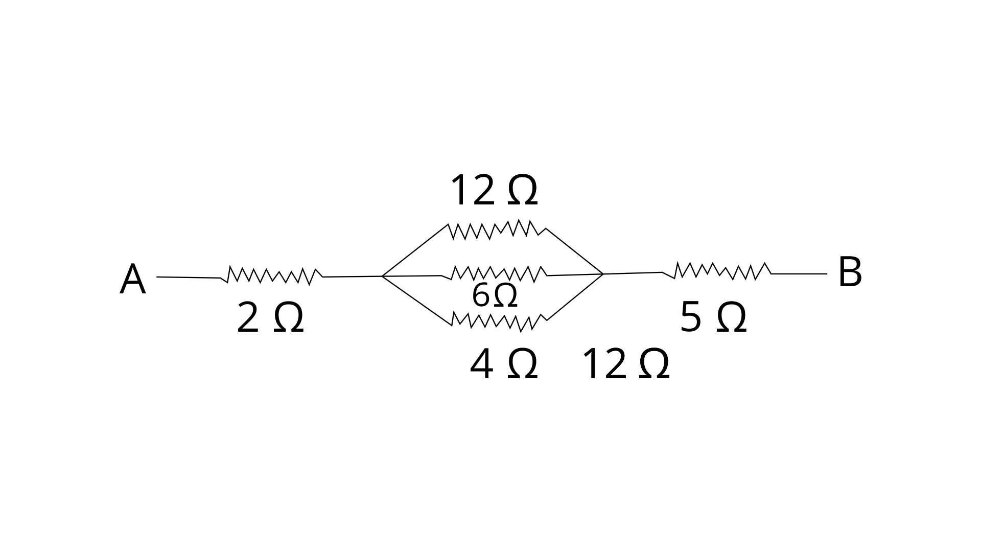
Ans:
In the given figure 12 Ω, 6 Ω and 4 Ω resistances are in parallel combination then their net resistances will be by formula -
1/R = 1/R1 + 1/R2 + 1/R3
1/R = 1/12 + 1/6 + 1/4
1/R = (1+2+3)/12 = 6/12 = ½
R = 2 Ω
Now this 2 Ω is in series with 2 ohm and 5 ohm
So equivalent resistance between points A and B will be -
RAB = 2 + R + 5 = 2 + 2 + 5 = 9 Ω
17. Calculate the equivalent resistance between the points A and B in figure.
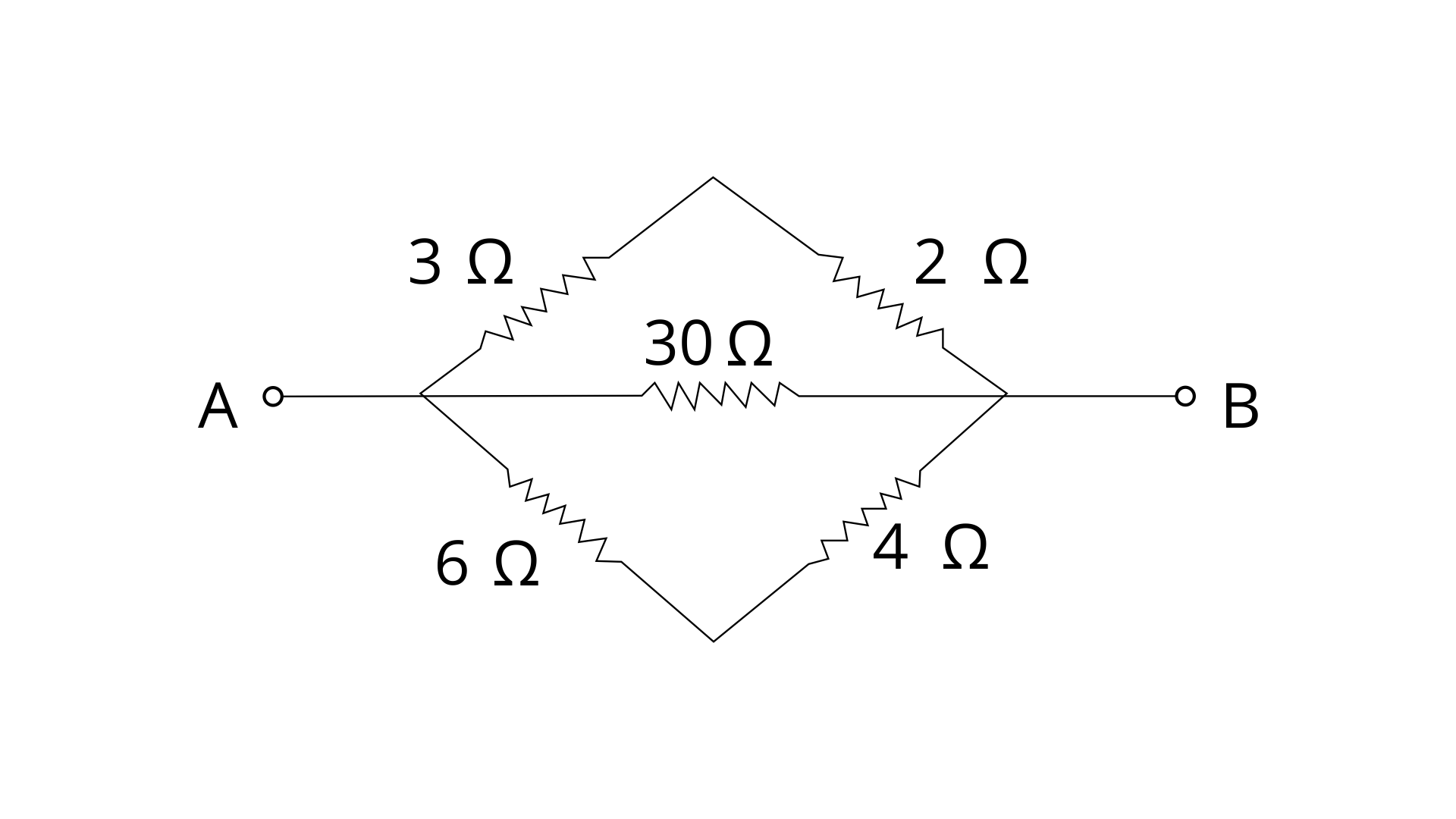
Ans: In the given figure we can see that the resistances 3 ohm and 2 ohm are in series in the upper so their net resistance is
R’ = 3 + 2 = 5 Ω
the resistances 6 ohm and 4 ohm are in series in the lower so their net resistance is
R’’ = 6 + 4 = 10 Ω
Now this R’, 30 ohm and R’’ are in parallel connection then equivalent resistance will be
1/R = 1/R1 + 1/R2 + 1/R3
1/R = 1/R’ + 1/30 + 1/R”
1/R = 1/5 + 1/30 + 1/10 = 10/30
R = 30 /10 = 3 Ω
18. In the network shown in fig., calculate the equivalent resistance between the points (a) A and B, and (b) A and C
Ans: (a) As we can see from the diagram RAD RDC RCB are in series connection so net resistance would be
R’ = 2 + 2 + 2 = 6 Ω
Now this 6 ohm resistance is in parallel with 2 ohm resistance
1/R = 1/R1 + 1/R2
equivalent resistance between the points A and B-
1/RAB = ⅙ + ½ = 4/6
RAB = 6/4 = 1.5 Ω
equivalent resistance between the points A and B is 1.5 ohm
(b) Resistance RADC = RAD + RDC = 2 + 2 = 4 Ω
Resistance RABC = RAB + RBC = 2 + 2 = 4 Ω
RADC and RABC are connected in parallel
1/R = ¼ + ¼ = ½
RAC = 2 Ω
equivalent resistance between the points A and C is 2 ohm
19. Five resistors, each of 3 Ω, are connected as shown in fig. 8.50. Calculate the resistance (a) between the points P and Q.
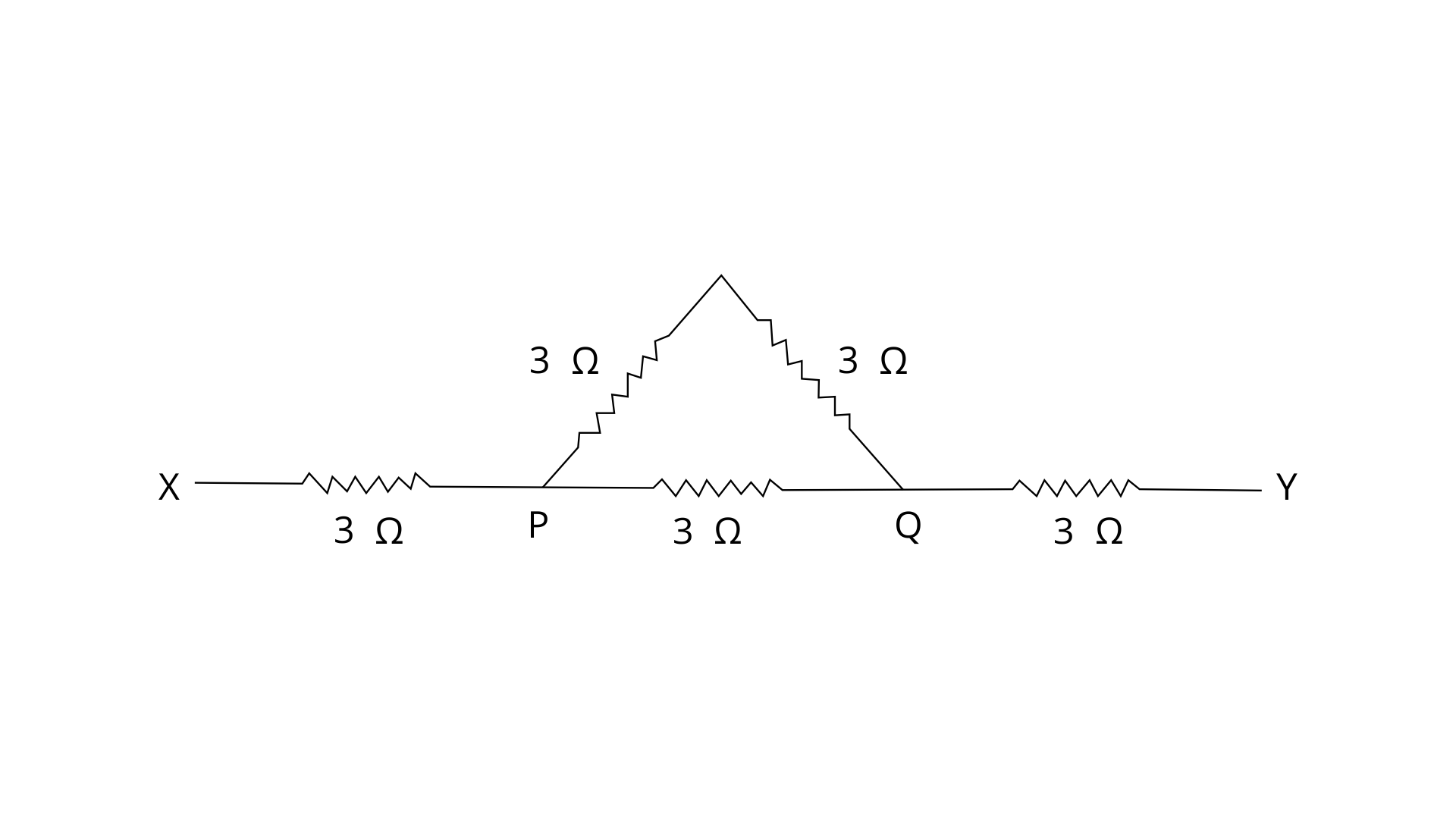
Ans: (a) Two resistance of 3 ohm of the triangle are in series connection -
R = 3 + 3 = 6 Ω
Now this 6 ohm is connected in parallel with 3 ohm (another resistance of triangle)
1/RPQ = ⅙ + ⅓ = ½
RPQ = 2 ohm
The resistance between the points P and Q will be 2 ohm
(b) Calculate the resistance between the points X and Y.
Ans: The resistance between the points X and Y - the resistance RXP , RPQ and RPQ are in series combination -
So RXY = RXP + RPQ + RPQ
RXY = 3 + 2 + 3 = 8 ohm
20. Two resistors of 2.0 and 3.0 are connected (a) in series, (b) in parallel, with the battery of 6.0 volt and negligible internal resistance. For each case draw a circuit diagram and calculate the current through the battery.
Ans: (a) When two resistors of 2 ohm and 3 ohm are connected in series

R1 =2 Ω
R2 =3 Ω
R = R1+R2 = 2 + 3 = 5 Ω
V = 6 V
Then by ohm law - V = IR
Current through the battery = I = V /R
I = 6 / 5 = 1.2 A
(b) When two resistors of 2 ohm and 3 ohm are connected in parallel-

R1 =2 Ω
R2 =3 Ω
1/R = 1/R1+ 1/R2
1/R = 1/2 + 1/3 = 5/6 Ω
R = 6/5 = 1.2 Ω
V = 6 V
Then by ohm law - V = IR
Current through the battery = I = V /R
I = 6 / 1.2 = 5 A
21. A resistor of 6 Ω is connected in series with another resistance of 4 V. A potential difference of 20 V is applied across a combination. Calculate:
(a) the current in the circuit, and
Ans: R1 = 6 Ω
R2 = 4 Ω
R = R1 + R2 = 6 + 4 (in series)
R = 10 Ω
V = 20 V (given)
I = V/R = 20/10 = 2 A
Current in the circuit will be 2 A
(b) the potential difference across the 6 Ω resistor.
Ans: R = 6 Ω
I = 2 A
V = ?
By ohm's law
V = IR = 6 × 2 = 12 V
Potential difference across the 6 Ω resistor will be 12 volt
22. Two resistors of resistance 4 Ω and 6 Ω are connected in parallel to a cell to draw current 0.5 A from the cell.
(a) Draw a labelled diagram of the arrangement
Ans: (a) Labelled diagram of the arrangement -
Equivalent resistance in parallel combination by formula -
1/R = 1/R1 + 1/R2
1/R = 1/4 + 1/6
R = 2.4 Ω
By ohm law -
V = IR
Given current = I = 0.5 A
V = 0.5 × 2.4 = 1.2 v
(b) Calculate the current in each resistor.
Ans: Current through R1 = 4 ohm
I = V / R1
I = 1.2 / 4 = 0.3 A
Current through R2 = 6 ohm
I = V / R1
I = 1.2 / 6 = 0.2 A
23. Calculate the current flowing through each of the resistors A and B in the circuit shown in fig.
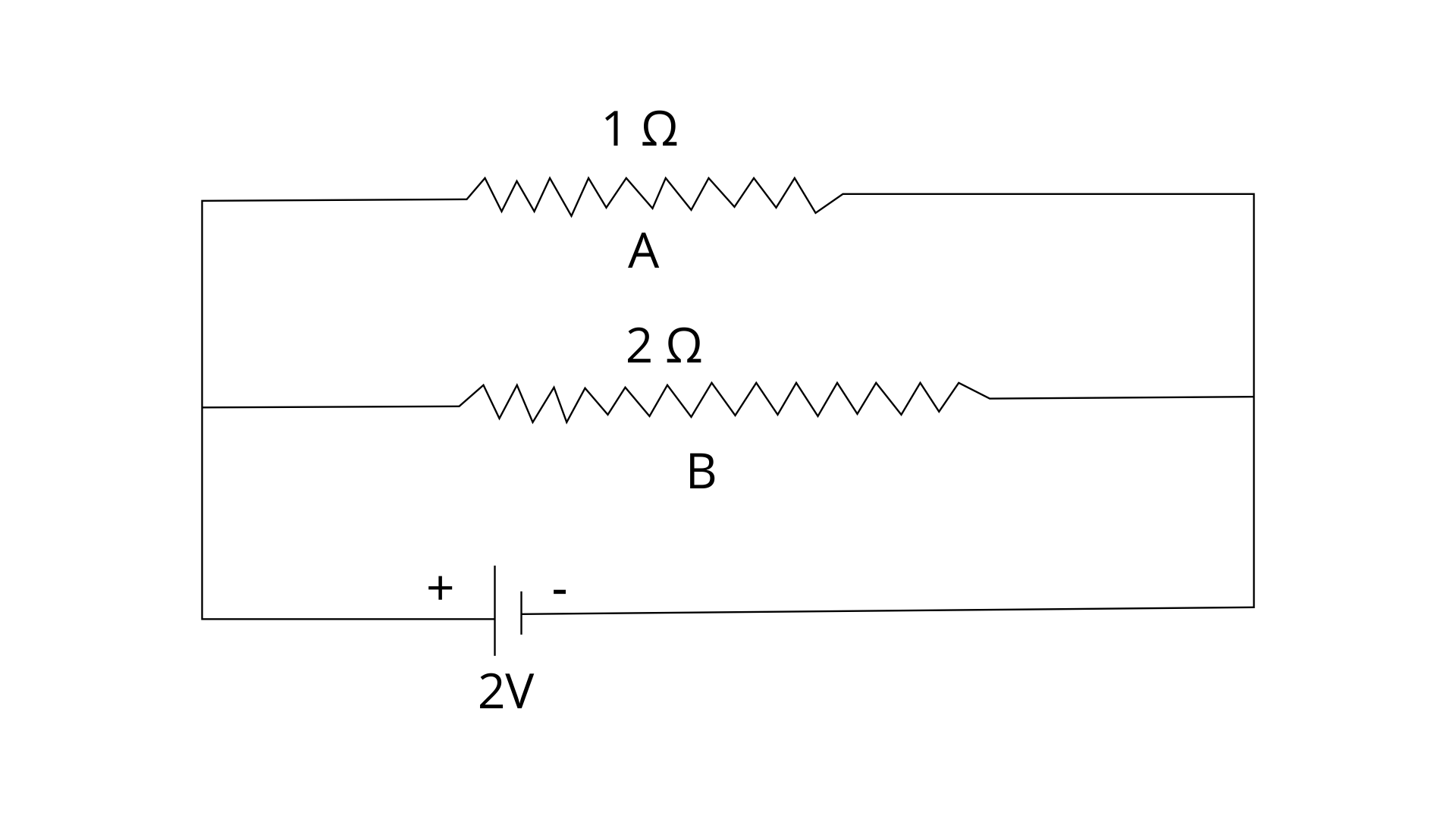
Ans: For resistor A:
R = 1 ohm
V = 2 V
Current through resistance 1 ohm = I = V/R = 2/1 = 2A
For resistor B:
R = 2 ohm
V = 2 V
Current through resistance 2 ohm I = V/R = 2/2 = 1A
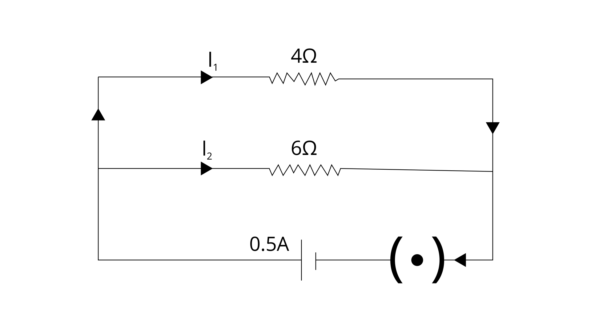
24. In fig., calculate:
(a) the total resistance of the circuit,
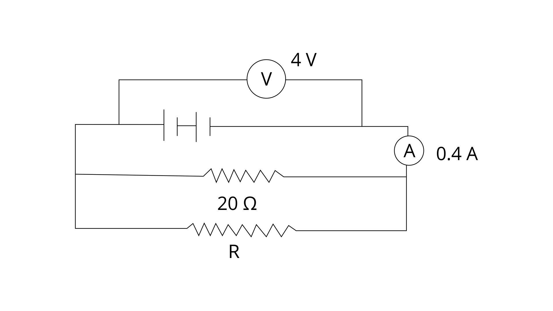
Ans: Given Voltage = V = 4 V
Current = I = 0.4 A
Total Resistance R' =?
By ohm law -
V = IR
Total Resistance = R' = V/I = 0.4/4 = 10 ohm
(b) the value of R, and
Ans: R1 = 20 ohm
R' = 10 ohm
1/R' = 1/R1 + 1/R
1 /10 = 1/20 + 1/R
1/R = 1/10 - 1/20 = 1/20
The value of R = R = 20 ohm
(c) the current flowing in R.
Ans: resistance R = 20 ohm
V = 4 V
current flowing in R = I = V/R = 4/20 = 0.2 A
25. A particular resistance wire has a resistance of 3.0 ohm per meter. Find: (a) The total resistance of three lengths of this wire each 1.5 m long, joined in parallel.
Ans: Resistance of 1m of wire = 3 ohm
Resistance of 1.5 m of wire = 3 × 1.5 = 4.5 ohm
Now they are joined in parallel combination -
1/R = 1/R1+ 1/R2 + 1/R3
1/R = 1/4.5 + 1/4.5 + 1/4.5
1/R = 3/4.5
R = 1.5 ohm
(b) The potential difference of the battery which gives a current of 2.0 A in each of the 1.5 m length when connected in parallel to the battery (assume that the resistance of battery is negligible)
Ans: current = I = 2 A
V = IR = 2 × 4.5 = 9 V
(c) The resistance of 5 m length of a wire of the same material, but with twice the area of cross section.
Ans: R = 3 ohm for 1 m
For 5 m length the resistance would be: R = 3 × 5 = 15 ohm
But Area A is double i.e. 2A and we know that Resistance is inversely proportional to cross sectional area so Resistance will be half.
R = 15/2 = 7.5 ohm
26. A cell supplies a current of 1.2 A through two 2 Ω resistors connected in parallel. When the resistors are connected in series, it supplies a current of 0.4 A. Calculate:
(i) the internal resistance and
Ans: when two 2 ohm resistance are connected in parallel
1/R = ½ + ½ = 1
R = 1 Ω
Current = I = 1.2 A (given)
By formula -
ε = I(R + r)
Here r is the internal resistance and ε is the emf.
ε = 1.2(1 + r) = 1.2 + 1.2 r
when two 2 ohm resistance are connected in series then
R = 2 + 2 = 4 Ω
Current in series connection = I = 0.4 A
ε = I(R + r) = 0.4(4 + r) = 1.6 + 0.4 r
By equating e.m.f.
1.2 + 1.2 r = 1.6 + 0.4 r
0.8 r = 0.4
r = 0.4 / 0.8 = ½ = 0.5 Ω
(i) Internal resistance r = 0.5 ohm
(ii) e.m.f. of the cell.
Ans: ε = I(R + r)
Put the value of r
ε = 1.2(1 + 0.5) = 1.8
e.m.f. of the cell = 1.8 volt
27. A battery of e.m.f. 15 V and internal resistance 3 Ω is connected to two resistors of resistances 3 Ω and 6 Ω connected in parallel. Find:
(a) the current through the battery,
Ans: 3 Ω and 6 Ω are in parallel so net resistance -
1/R = 1/3 + 1/6 = 1/2
So R = 2 Ω
Internal resistance = r = 3 Ω (given)
E.m.f. = ε = 15 V (given)
By formula -
Put all the known values we can get current through the battery
ε = I(R + r)
15 = I(2 + 3)
I = 15/5 = 3 A
(b) the p.d. between the terminals of the battery.
Ans: p.d. between the terminals of the battery = V = ?
R = 2 Ω
V = IR = 3 × 2 = 6 V
(c) the current in 3 Ω resistor,
Ans: Potential difference = V = 6 V
R = 3 Ω
Current in 3 Ω resistor = I = V/R = 6/3 = 2 A
(d) the current in the 6 Ω resistor.
Ans: Potential difference = V = 6 V
R = 6 Ω
Current in 6 Ω resistor = I = V/R = 6/6 = 1 A
28. The circuit diagram in fig 8.53 shows three resistors 2Ω, 4Ω and RΩ connected to a battery of e.m.f. 2V and internal resistance 3Ω if main current of 0.25 A flows through the circuit, find:
(a) the p.d. across the 4Ω resistor,
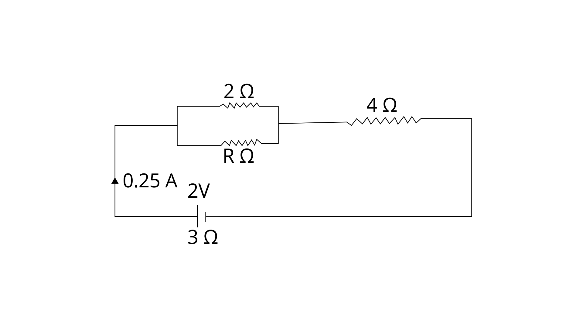
Ans: R = 4 Ω
Current in the circuit = I = 0.25 A (given)
From ohm's law -
V = IR = 0.25 × 4 = 1 V
The p.d. across the 4Ω resistor will be 1 volt
(b) the p.d. across the internal resistance of the cell,
Ans: Internal Resistance r = 3 Ω (given)
I = 0.25 A (given)
V = IR = 0.25 × 3 = 0.75 V
The p.d. across the internal resistance of the cell will be 0.75 volt
(c) the p.d. across the RΩ or 2Ω resistor, and
Ans: Effective resistance of parallel combination of two 2 Ω resistances is 1 Ω
V = I/R
Voltage across parallel combination -
I = 0.25 A (given)
V = IR = 0.25 × 1 = 0.25 Volt
(d) the value of R.
Ans: Current = I = 0.25 A (given)
ε = 2V, internal resistance = r = 3 Ω
By formula -
ε = I(R' + r)
2 = 0.25(R' + 3)
R' = 5 Ω
R' - 4 Ω = parallel combination of R and 2 Ω (by the given diagram)
1 Ω = 1/R + ½
1/R = 1- ½ = ½
R = 2 Ω
29. Three resistors of 6.0 Ω, 2.0 Ω and 4.0 Ω are joined to an ammeter A and a cell of emf 6.0 V as shown in fig 8.52 Calculate:
(a) the effective resistance of the circuit and
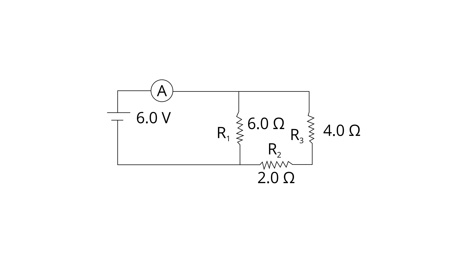
Ans:
(a) Given R1 = 6 Ω, R2 = 2 Ω , R3 = 4 Ω
R' = R2 + R3 = 2 + 4 = 6 Ω ( R2 and R3 are in series )
Now this R1 and R' in parallel:
1/ R = 1/ R1 + 1/R'
1/R = 1/6 + 1/ 6 = 2/6
R = 3 Ω
Effective resistance of the circuit = 3 ohm
(b) the reading of the ammeter.
Ans: the reading of ammeter -
R = 3 Ω
V = 6 V
Current = I = ?
From ohm law
I = V/R = 6/3 = 2 A
Reading of ammeter - 2 ampere
30. The diagram below in Fig. shows the arrangement of five different resistances connected to a battery of e.m.f. 1.8 V Calculate:
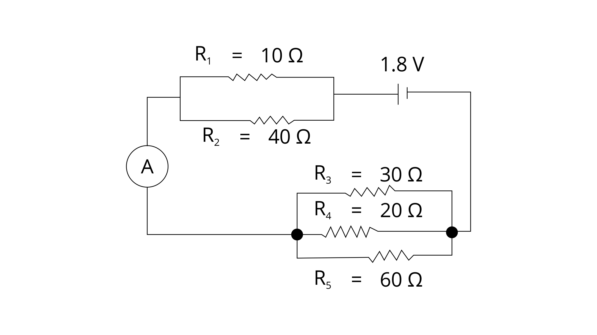
(a) the total resistance of the circuit, and
Ans:

(a) In the figure above,
Let resistance between X and Y be Rxy then, by formula of resistance in parallel combination -
1/Rxy = 1/10 + 1/ 40 = 5/40
Rxy = 8 Ω
Or, R 8 Ω
Let RAB be the net resistance between points A and B. Then by formula of resistance in parallel combination -
1/RAB = 1/30 + 1/ 20 + 1/60 = 6/60
RAB = 10 Ω
∴ Total resistance of the circuit = 8Ω + 10Ω = 18Ω (8 and 1o ohm are in series )
(b) the reading of ammeter A.
Ans: By ohm law -
Current = I = Voltage /total resistance
I = 1.8 / 18 = 0.1 A
So the reading of ammeter would be 0.1 A
31. A cell of emf 2V and internal resistance 1.2 ohm is connected to an ammeter of resistance 0.8 ohm and two resistors 4.5 ohm and 9 ohm as shown in fig.
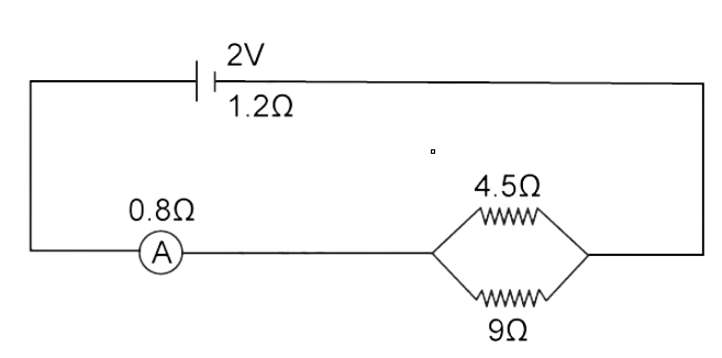
Find: (a) the reading of the ammeter,
Ans: Given: emf = 2V,
Internal resdiatnce = r = 1.2Ω,
Resistance of ammeter = RA = O.8Ω,
R1 = 4.5Ω , R2 = 9Ω
R1 and R2 are in parallel -
1/Rp = 1/R1 + 1/R2
1/Rp = 1/4.5 + 1/9 = ⅓
Rp = 3 Ω
We know that for the circuit the total resistance of the circuit is -
R total = Rp + r + RA
R total = 3 + 1.2 + 0.8 = 5Ω
Hence, the current through the ammeter is I = V/Rtotal
I = 2/5 = 0.4A
(b) the potential difference across the terminals of the cell.
Ans: The potential difference across the terminals of the cell is
Vcell = emf - IRcell
Vcell = 2 – (0.4 × 1.2)
Vcell = 2 - 0.48
Vcell = 1.52 V
(c) the potential difference across the 4.5 resistor.
Ans: The potential difference across the 4.5 resistor is -
V = Vcell - Vammeter
V = 1.52 – (0.4 × 0.8)
V = 1.52 - 0.32 = 1.2 V
Exercise (8C)
1. Write an expression for the electrical energy spent in flow of current through an electrical appliance in terms of current, resistance and time.
Ans: H = I2 Rt
Where H is the electrical energy produced in the appliance.
I is the amount of current flowing through appliances
R is the resistance
And t is the time for which the current flows.
2. (a) Write an expression for the electrical power spent on flow of current through a conductor in terms of resistance and potential difference.
Ans: P=V2/R
here P is electrical power in a conductor
V is the potential difference across the conductor and R is the resistance across the same.
(b) Write an expression for the electrical power spent on flow of current through a conductor in terms of current and resistance.
Ans: P = I2R where P is electrical power in a conductor
R is the resistance across the conductor and I is the current through the conductor.
3. Electrical power P is given by the expression P = (Q × V) / time
(a) What do the symbols Q and V represent?
Ans: Q here represents the charge whereas V is the voltage difference across the conductor.
(b) Express the power P in terms of current and resistance explaining the meaning of symbols used there in.
Ans: P=VI, here P is electrical power in a conductor
V is the potential difference across the conductor and I is the current through the conductor.
4. Name the S.I. unit of electrical energy. How is it related to Wh?
Ans: The S.I. the unit of electrical energy is Joule.
1Wh= 3600J
5. Explain the meaning of the statement that the power of an appliance is 100W.
Ans: Power = Energy produced/time
If the power of the appliance is 100W it means 100J of electrical energy is consumed by the appliance in 1 secs.
6. State the S.I. unit of electrical power.
Ans: The S.I. the unit of electrical power is Watt.
Power is defined as the product of Voltage and current. When 1A current is produced by the potential difference of 1V across the circuit then the resulting power produced in the same is 1 Watt.
7. (i) State and define the household unit of electricity.
Ans: kWh is the household unit of electricity. It’s defined as the energy consumed by the device of the power 1 kilowatt operated for 1hr.
(ii) What is the voltage of the electricity that is generally supplied to a house?
Ans: Generally for domestic appliances 220V is the amount of voltage that is supplied.
(iii) What is consumed while using different electrical appliances, for which electricity bills are paid.
Ans: Electrical energy is the quantity that’s consumed by using different appliances for which the electricity bills are paid.
8. (i) Name the physical quantity which is measured in kW.
Ans: (i) Power is usually measured in kW.
(ii) Name the physical quantity which is measured in kWh.
Ans: Electrical energy is measured in kWh as kWh is the commercial unit of electricity.
(iii) Name the physical quantity which is measured in Wh.
(iii) Electrical energy is the physical quantity that’s measured in Wh.
9. Define the term kilowatt-hour and state its value in S.I. unit.
Ans: kilowatt-hour is the commercial unit of electricity. It’s defined as the energy consumed by the device of the power 1 kilowatt operated for 1hr.
1kWh = 3.6 × 10⁶ J
10. How do kilowatt and kilowatt-hour differ?
Ans: kilowatt refers to the unit of electrical power whereas kilowatt-hour is the unit of electrical energy.
11. Complete the following:-
(a) 1 kWh = 1 volt × 1 ampere × ………./1000
Ans: 1 kWh = 1 volt × 1 ampere × 1000/1000
(b) 1 kWh = ……….J
Ans: 1kWh = 1000J
12. What do you mean by power rating of an electrical appliance? How do you use it to calculate (a) the resistance of the appliance?
Ans: The power rating of any electrical appliance means the exact value of voltage upon which the device actually works. Example if a device is written with the power rating of 60W-230V it means 230V is the voltage at which the device will operate and it will consume power of 60W.
(a) The resistance of the appliance is calculated by the formula
R=V2/P
Here V is the voltage rating on the appliance and P is the power rating on the appliance.
(b) How do you use it to calculate the safe limit of current in it and while in use?
Ans: Safe limit of current is calculated by the formula
I=P/V
=Power rating on the appliance/Voltage rating on the appliance.
13. An electric bulb is rated ‘100W, 250V’. What information does this convey?
Ans: This statement means if the bulb is operated at 250V then it will consume electrical power of 100W or 100J of electrical energy in 1 secs.
14. List the names of three electrical gadgets used in your house. Write their power, voltage rating and approximate time for which each one is used in a day. Hence find the electrical energy consumed by each in a month of 30 days.
Ans: Electric heater with the power rating as 1000W, Electric mixer with power rating as 750W and Refrigerator with the power rating 150W are some of the electrical gadgets used often in home. All these devices work on the domestic supply of 220V for 1hour daily.
In order to calculate the electrical energy consumed by each of them for a month of 30 days
Electric heater:- Power = 1000W
Time for which it’s used daily = 1hr
Power = Electrical energy consumed/time
Hence Electrical energy = Power × time
= 1000 W × 1 hr × 30 = 30000 Wh (for the month of 30 days)
Similarly for electric mixer Power = 750W
Time for which it’s used daily = 1hr
Power = Electrical energy consumed/time
Hence Electrical energy = Power × time
= 750 W × 1 hr × 30 = 22500 Wh (for the month of 30 days)
For Refrigerator Power = 150W
Time for which it’s used daily = 1hr
Power = Electrical energy consumed/time
Hence Electrical energy = Power × time
= 150 W × 1 hr × 30 = 4500Wh (for the month of 30 days)
15. Two lamps, one rated 220V, 50W and the other rated 220V, 100W, are connected in series with mains of voltage 220V. Explain why the 50W lamp consumes more power.
Ans: Power = I2/R here I is the current flowing through the lamp and R is the resistance. Since both the lamps are connected in series, current flowing through both will be the same, which means P∝1/Resistance
Hence 50W consumes more power than 100W as it’ll be having less resistance than the other bulb.
16. Name the factors on which the heat produced in a wire depends when current is passed in it, and state how it depends on the factors stated by you.
Ans: Heat produced in a wire depends on the following factors according to the relation H = I2 Rt
a) Current flowing through the wire(I)
b) Resistance across the wire(R)
c) time for which the current flows(t)
The heat produced is directly proportional to the square of current flowing through it. More is the current flowing, the more heat will be generated.
Similarly the heat produced is also directly proportional to the resistance of wire and the time for which current flows through the wire.
Multiple Choice Type
1. When a current flows through a resistance R for time t, the electrical energy spent is:
(a) IRt
(b) I2Rt
(c) IR2t
(d) I2R/t
Ans: Correct option is (b)I2Rt
This is the formula for Joule’s law of Heating.
2. An electrical appliance has a rating 100W,120V. The resistance of element of appliance when in use is:
(a) 1.2Ω
(b)144Ω
(c) 120Ω
(d) 100Ω
Ans: Correct option is (b) 144Ω
Given Power = 100W, Potential difference = 120V
According to the formula P=V2/R
Hence R = V2/P
=(120)2/100 = 144Ω
Numericals
1. An electric bulb of resistance 500Ω draws a current of 0.4A from the source. Calculate: (a) power of the electric bulb.
Ans: Resistance = 500Ω
Current (I) = 0.4A
Power = I2R
Hence it’s equal to (0.4)2 × 500 = 80W
(b) Calculate the potential difference at its end.
Ans: According to Ohm’s law V=IR
= 0.4×500 = 200V
2. A current of 2A is passed through a coil of 75Ω for 2 minutes.(a) How much heat energy is produced?
Ans:(a) Resistance = 75Ω
Current (I) = 2A
Time for which current flows (t) = 2mins = 2×60 = 120secs
Heat produced = I2Rt
Hence it’s equal to (2)2×75×120 = 36000J or 36kJ
(b) How much charge is passed through the resistance?
Ans: Current (I) = 2A
Time for which current flows (t) = 2mins = 2×60 = 120secs
I = Q/t
Where Q is the charge flowing through the resistance
Therefore Q =It = 2×120= 240C
3. Calculate the current through a 60W lamp rated for 250V. If the line voltage falls to 200V, how is the power consumed by the lamp affected?
Ans: Given Power = 60W, Potential difference = 250V
According to the formula P=V2/R
Hence R = V2/P
= (250)2/60 = 1041.67Ω
Similarly when the voltage falls to 200V the resistance of the lamp will remain same hence the new power will be
P’=(V’)2/R
where V’ is the new voltage = 200V
=(200)2/1041.67
=38.4W
Hence the power consumption reduces to 38.4W
4. An electric bulb is rated ‘100W, 250V’. How much current will the bulb draw if connected to a 250V supply?
Ans: Given Power = 100W, Potential difference = 250V
According to the formula P=VI
Where I is the current flowing through the bulb
Hence 100 = 250×I or I = 100/250 = 0.4A
The current flowing through the electric bulb is 0.4A.
5. An electric bulb is rated ‘220V, 100W’. (a) What is its resistance?
Ans: Given Power = 100W, Potential difference = 220V
According to the formula P=V2/R
Hence R = V2/P
= (220)2/100 =484Ω
(b) What safe current can be passed through it?
Ans: The safe current is calculated by the formula P=VI
Where I is the current flowing through the bulb
Hence 100=220×I or I = 100/220 = 0.45A
6. A bulb of power 40W is used for 12.5h each day for 30 days. Calculate the electrical energy consumed.
Ans: Given Power = 40W
Time = 12.5hr
According to the formula P=Energy produced /time
Hence electrical energy = P×time
= 40×12.5 = 500Wh.
This energy consumption is for a single day. For 30 days the total electrical energy consumed will be 500×30 = 15000Wh or 15kWh.
7. A bulb of press is rated ‘750W, 230V’. Calculate the electrical energy consumed by the press in 16 hours.
Ans: Given Power = 750W, Potential difference = 230V
According to the formula P=Energy produced /time
Hence electrical energy = P×time
= 750×16 = 12000Wh or it can be written as 12kWh.
8. (i) An electrical appliance having a resistance of 200Ω is operated at 200V. Calculate the energy consumed by the appliance in 5 minutes in joules
Ans: Given Resistance = 200Ω, Potential difference = 200V
According to the formula P=V2/R
Hence P = (200)2/200
= 200W
Time for which the appliance works = 5 mins = 5×60 = 300 secs
(i) According to the formula P=Energy produced / time
Hence electrical energy = P×time
= 200×300 = 60000J
(ii) Calculate the energy consumed by the appliance in 5 minutes in kWh.
Ans: As per the conversion 1kWh = 3600000J
So 60000 J in kWh will be = 60000J/3600000 J = 0.167kWh
9. A bulb rated at 12V, 24W operates on a 12 volt battery for 20 minutes. Calculate:
(i) the current flowing through it.
Ans: Given Power = 24W, Potential difference = 12V
time for which current flows = 20 mins = 20×60 = 1200secs
(i) According to the formula P=VI
Where I is the current flowing through the bulb
24=12×I or I =24/12 = 2A
(ii) Calculate the energy consumed.
Ans: (ii) P=Energy produced /time
Hence electrical energy = P×time
= 24×1200 = 28800J
10. A current of 0.2A flows through a wire whose ends are at potential difference of 15 V. Calculate
(i) the resistance of the wire.
Ans: Given Potential difference = 15V
Current flowing through wire = 0.2A
(i) According to Ohm’s law V=IR
Where R is the resistance of wire hence
15 = 0.2×R or R = 15/0.2 = 75Ω
(ii) the heat energy produced in 1 minute.
Ans: Heat produced in wire H= I2Rt
Time for which current flows = 1min = 60 secs
H=(0.2)2×75×60 = 180J
11. What is the resistance, under normal working conditions, of an electric lamp rated ‘240V, 60W’? If two lamps are connected in series across a 240V mains supply, explain why each one appears less bright.
Ans: Given Power = 60W, Potential difference = 240V
According to the formula P=V2/R
Hence R = V2/P
= (240)2/60 =960Ω
By Ohm’s law V=IR
Where I is the amount of current flowing through lamp
I=240/960 = 0.25A
If two lamps are connected in series then the current through each bulb will be 0.25/2 = 0.125 A due to which each one will appear less bright as the heat dissipation across each bulb will be one fourth
H(through each bulb) = (I/2)2Rt = Rt/4
12. Two bulbs are rated ‘60W, 220V’ and ‘60W, 110V’ respectively. Calculate the ratio of the resistances.
Ans: Given Power = 60W, Potential difference = 220V
According to the formula P=V2/R
Hence R = V2/P
= (220)2/60 =806.67Ω
For the second case Power (P’) = 60W, Potential difference (V’)= 110V
According to the formula P’=(V’)2/R’
Hence R’ = (V’)2/P’
= (110)2/60 =201.67Ω
Finally R/R’= 806.67/201.67 = 3.99:1 or ~4:1
The ratio of the resistances is 4:1.
13. An electric bulb is rated ‘250W, 230V’. Calculate:
(i) the energy consumed in one hour.
Ans:
(i) Given Power = 250W, Potential difference = 230V
Time for which bulb glows = 1hr
According to the formula P=Energy produced /time
Hence electrical energy = P×time
= 250×1 = 250Wh
As 1Wh = 3600J so 250Wh = 250×3600 = 9×10⁵J
(ii) Calculate the time in which the bulb will consume 1.0kWh energy when connected to 230V mains.
Ans: Given electrical energy = 1.0kWh = 1000Wh
Power = 250W hence P=Energy produced /time
= 1000Wh/250 = 4hrs
14. Three heaters each rated ‘250W, 100V’ are connected in parallel to a 100V supply.
(i) Calculate the total current taken from the supply.
Ans: Given Power = 250W, Potential difference = 100V
(i) According to formula P=VI
Where I is the current flowing
250 = 100 × I or I = 250/100 = 2.5A
(ii) Calculate the resistance of each heater.
Ans: Since all the three resistors are connected in parallel the voltage across each of them will be same
P=V2/R
R=V2/P =(100)2/250 = 40Ω
This 40Ω is the resistance of each heater.
(iii) Calculate the energy supplied in kWh to the three heaters in 5hours.
Ans: P=Energy produced /time
Hence electrical energy = P×time
= 250×3×5 = 3750Wh or 3.75kWh
15. A bulb is connected to a battery of p.d. 4V and internal resistance 2.5Ω. A steady current of 0.5A flows through the circuit.
(i) Calculate the total energy supplied by the battery in 10 minutes.
Ans: Given internal resistance = 2.5Ω , Potential difference = 4V
Current = 0.5A
Time for which bulb glows = 10mins = 10×60 = 600secs
Power is calculated as P=VI
=4×0.5 = 2W
According to the formula P=Energy produced /time
Hence electrical energy = P×time
=2×600 = 1200J or 1.2kJ
(ii) Calculate the resistance of the bulb
Ans: According to Ohm’s law V=IR
Or R =V/I = 4/0.5 = 8Ω
Resistance of the bulb(R’) = Total resistance of battery - internal resistance =8-2.5 = 5.5Ω
(iii) Calculate the energy dissipated in the bulb in 10 minutes.
Ans: Energy dissipation in bulb = I2R’t
=(0.5)2×5.5×600 = 825J
16. Two resistors A and B of resistance 4Ω and 6Ω respectively are connected in parallel. The combination is connected across a 6 volt battery of negligible resistance.
(i) Calculate the power supplied by the battery.
Ans: Given RA = 4Ω, RB = 6Ω
Since both are connected in parallel combination hence R(eq) = 4×6/4+6
= 24/10 = 2.4Ω
Potential difference = 6V
(i) Power supplied by the battery P = V2/R
= (6)2/2.4 = 15W
(ii) Calculate the power dissipated in each resistor.
Ans: Power dissipated in each resistor
As the resistances are connected in parallel combination the potential difference across the resistances will be the same.
Hence PA = V2/RA = (6)2/4 = 9W
Similarly PB = V2/RB = (6)2/6 = 6W
17. A battery of emf 15V and internal resistance 2Ω is connected to two resistors of resistance 4 ohm and 6 ohm joined in series. Find the electrical energy spent per minute in a 6 ohm resistor.
Ans: Given R1 = 4Ω, R2 = 6Ω
Since both are connected in series combination hence R(eq) = 4+6 +2= 12Ω
Potential difference = 15V
According to Ohm’s law V=IR
Where I is the current flowing through the battery
15 = 12×I or I = 15/12 = 1.25A
Voltage across 6ohm resistor = 1.25×6 = 7.5V
Electrical energy spent per minute = V2(t)/R
= (7.5)2×(60)/6
= 562.5J
Hence the electrical energy spent per minute in 6ohm resistor is 562.5J
18. Water in an electric kettle connected to a 220V supply takes 5 minutes to reach its boiling point. How long will it take if the supply voltage falls to 200V?
Ans: Heat required by the electric kettle to boil water = V2(t)/R
Since the resistance of kettle is same in both cases therefore,
V12(t1) = V22(t2)
(220)2×5 = (200)2×(t2)
(t2)= [(220)2×5]/(200)2 = 6.05 minutes
19. An electric toaster draws 8A current in a circuit with a source of 220V. It is used for 2h. Find the cost of operating the toaster if the cost of electrical energy is ₹4.50 per kWh.
Ans: Given Current = 8A, Potential difference = 220V
time for which current flows = 2h
According to the formula P=VI
Hence P = 8×220 = 1760W
Also P = Energy produced /time
Hence electrical energy = P×time
= 1760×2 = 3520Wh or 3.52kWh
Cost of consuming energy per kWh is ₹ 4.50
Total cost of consuming 3.52 units = ₹ 4.50 × 3.52 = ₹ 15.84 (∵1kWh = 1unit)
20. An electric iron is rated 220V, 2kW. If the iron is used for 3h daily, find the cost of running it for one week if it costs ₹ 4.25 per kWh.
Ans: Given Power = 2kW = 2000W, Potential difference = 220V
time for which current flows = 3h
According to formula P = Energy produced /time
Hence electrical energy = P×time
= 2000×3 = 6000Wh or 6kWh
Cost of consuming energy per kWh is ₹ 4.25
Total cost of consuming 6 units for 1 week = ₹ 4.25 × 7 × 6 = ₹ 178.5 (∵1kWh = 1unit)
21. A geyser is rated ‘1500W, 250V’. This geyser is connected to 250V mains.
(i) Calculate the current drawn.
Ans: Given Power = 1500W, Potential difference = 250V
time for which current flows = 50hrs
(i) According to the formula P=VI
Where I is the current flowing through the bulb
1500 = 250 × I or I = 1500/250 = 6A
(ii) Calculate the energy consumed in 50 hours.
Ans: Also P = Energy produced /time
Hence electrical energy = P × time
= 1500×50 = 75000Wh or 75kWh
(iii) Calculate the cost of energy consumed at ₹ 4.20 per kWh.
Ans: Cost of consuming energy per kWh is ₹ 4.20
Total cost of consuming 75 units = ₹ 4.20 × 75 = ₹ 315 (∵1kWh = 1unit)
Current Electricity Solutions for Class 10 Physics
Physics is one of the most difficult courses in ICSE Class 10 because it covers all chapters. The textbook's chapters are difficult, and students frequently become perplexed as to which approach is the best. Selina Physics Chapter 8 Current Electricity Solutions for ICSE Class 10 are provided by Vedantu so that students may prepare effectively for their exams. Our professionals, who have extensive academic knowledge, have produced all of the Selina Physics solutions.
Concise Physics Class 10 by Selina Solutions is produced in compliance with the ICSE board. These precise answers aid students in exam preparation because they are well-structured and tailored to their specific comprehension abilities. The use of simple language in Selina Solutions increases students' enthusiasm in understanding the concepts discussed in the chapter. Students can get the Selina Solutions Concise Physics Class 10 PDF for free by clicking on the links below.
Our Selina ICSE solutions serve as step-by-step guidance and are necessary for exam preparation. Selina ICSE Chapter 8 Current Electricity Solutions for Class 10 can assist you in better understanding topics so that you may study at any time and from any location. Selina Physics ICSE Solutions Class 10 is accessible for free and covers all of the topics in depth. Our Selina ICSE Physics solutions for Class 10 serve as a free guide to help you get ahead in school.
The Selina answers for Class 10 may be obtained free of charge from our website with a single click in order to assist more students in preparing for this topic and scoring well in Class 10 board examinations.
Selina Concise Physics answers for Class 10 are ideal for board examination preparation. The ICSE Class 10 course is extensive, and students must put up a serious effort in order to pass the tests. The Selina simple physics Class 10 ICSE answers pdf contains information on all of the subject's chapters. Each explanation includes all of the assumptions and logic that were utilized to arrive at the result. Even if they are practicing for the first time, pupils will be able to explore and grasp each idea.
The following issues will be discussed in this chapter:
Charged with electricity
(definition; charge on a macro body; forms of electric charge; body charging; electric charge attributes; a unit of charge)
The electricity that is both static and current (state electricity; current electricity)
Electric potential and electric field (electric field; electric potential; electric potential difference)
The movement of electricity (charge in motion; a unit of current; the direction of electric current; how the current flows in a wire; how to get a continuous flow of electric current)
Circuits of electricity (open electric circuit; closed circuit)
Electrical resistance (ohm's law; a conductor's resistance; a unit of resistance; factors affecting a conductor's resistance; resistivity; conductivity)Conductors, resistors, and insulators are all used in electronic circuits.


FAQs on Current Electricity Solutions for ICSE Board Class 10 Physics
1. What is resistance?
The obstruction or hindrance offered by any conductor to the flow of electric current is called resistance. In general, all metals exhibit resistance to the flow of electric current to some extent. The resistance of a conductor is measured in Ohms (), that is, volts per ampere. Resistors are one of the most important components of electric circuits.
2. What is Ohm’s law?
Ohm’s law expresses the relationship between the voltage and electric current. It states that when a voltage is applied across the two ends of any conductor, and a current flows through it, the current is directly proportional to the voltage. Ohm’s law can be expressed as follows.
V = IR, where R is the resistance offered by a conductor.
Ohm’s law is one of the most crucial topics covered in the ICSE Board Class 10 Current Electricity chapter. Numerical value type questions based on the concept of Ohm’s law are commonly asked in the ICSE Class 10 board exams.
3. On which factors does the resistance of a conductor depend?
The resistance of a conductor is expressed as:
R= lA
The factors on which the resistance of a conductor depends are listed below.
The length of the conductor.
The area of cross-section of the conductor.
The material of the conductor.
The temperature of the conductor.
The resistance of a conductor is directly proportional to its length, and resistivity, and inversely proportional to its cross-sectional area. The resistivity of a conductor is dependent upon the material of the conductor.
4. What is Electric Current according to Current Electricity Solutions for Class 10 Physics ICSE Board (Concise - Selina Publishers)?
Electric current, electric circuit, voltage or electric potential, resistance, and (Ohm's law) are all terms used to describe electricity.
Electric current is the movement of electric charge via a conductor, and it is carried by moving electrons.
Electric current, by convention, runs in the opposite direction of electron movement.
A continuous and closed path of electric current is referred to as an electric circuit.
The letter 'I' stands for electric current. Electric current is expressed as the rate of flow of electric charges. The rate of flow refers to the amount of charge that moves through a specified region in a given amount of time.
Electric circuits are defined as a continuous and closed route of electric current.
Electric current is represented by the letter 'I.' Electric current is expressed as the rate of flow of electric charges. The rate of flow refers to the amount of charge that moves through a specified region in a given amount of time.
5. How can I get good grades in Physics in Class 10?
Getting good grades solely depends upon the preparation you do. To get good grades in physics, you need to have a very clear understanding, which you may get by reading the textbook and using the Vedantu Class 10 Physics Notes. Read the theoretical section of the chapter and make a list of all relevant formulas and bullet points to include in your notes. Start completing a few numerical-based questions once you've properly grasped the chapter; this will help you develop conceptual clarity.