


Machines Solutions for Class 10 Physics ICSE Board (Concise - Selina Publishers)
Exercise 3(A)
1. (a) What do you understand about a simple machine ?
Ans: A simple machine is a device that has few or no moving parts in it. A machine is a device by which we can either overcome a large resistive force or a load at some point by applying a small force at a convenient point and in a desired direction or by which we can obtain a gain in speed.
(b) State the principle of an ideal machine.
Ans: Principle of an ideal machine - An ideal machine is that in which there is no energy dissipation means no loss of energy
For ideal machine - output energy = input energy
So work output is equal to work input so efficiency of the ideal machine would be 100 %.
2. State four ways in which machines are useful to us.
Ans: Machines are very useful to us in the following ways which are given below-
(1) By using machines we can lift heavy loads with less effort.
(2) We can change the point of application of effort to our convenient point.
(3) We can change the direction of effort to a convenient direction also.
(4) We can gain speed with the help of machines.
3. Name a machine for each of the following use —
(a) To multiply the force,
Ans: To multiply force - a jack, it is used to lift a car.
(b) To change the point of application of force,
Ans: To change the point of application of force - by applying the force on the pedal, we can rotate the wheel of a cycle with the help of a chain that is attached to the wheel.
(c) To change the direction of force,
Ans: To change the direction of force - To lift a bucket full of water from the well, a single fixed pulley is used. We applied force or efforts in the downward direction rather than upwards direction. When there is no pulley then we have to apply force in the upward direction so we can change the direction of force with the help of pulley.
(d) to obtain the gain in speed.
Ans: To obtain gain in speed - A knife. By a small displacement of its handle, the blade of a knife moves longer so that it gains speed.
4. What is the purpose of jack in lifting a car by it?
Ans: The purpose of jack, a mechanical lifting device is to make the effort and force less than the load. It works as a force multiplier so that a heavy load like a car can be lifted with little effort on the jack.
5. What do you understand about an ideal machine? How does it differ from a practical machine?
Ans: An ideal machine is a machine, there is no friction between the parts of it. An ideal machine in which there is no energy dissipation means no loss of energy.
For ideal machine - output energy = input energy
So work output is equal to work input so efficiency of the ideal machine would be 100 %.
In a practical machine output energy is not equal to input energy like an ideal machine. It is always less than the input energy because of some energy loss which is not the case in an ideal machine. The efficiency of a practical machine is always less than 100 %.
6. Explain the term mechanical advantage. State its unit.
Ans: The ratio of the load to the effort or force is called mechanical advantage of the machine. It has no unit.
So, Unit of mechanical advantage - unitless
7. Define the term velocity ratio. state its unit.
Ans: Velocity ratio is the ratio of the velocity of effort to the velocity of the load is called the velocity ratio of the machine. It has no unit so it is unitless.
8. How is mechanical advantage related to velocity ratio for an ideal machine?
Ans: An ideal machine is a machine, there is no friction between the parts of it. An ideal machine in which there is no energy dissipation means no loss of energy.
For ideal machine - output energy = input energy
So work output is equal to work input so efficiency of the ideal machine would be 100 %.
Velocity ratio is the ratio of the velocity of effort to the velocity of the load is called the velocity ratio of the machine.
The ratio of the load to the effort or force is called the mechanical advantage of the machine.
For an ideal machine, the mechanical advantage is equal to the velocity ratio.
9. Define the term efficiency of a machine. Give two reasons for a machine not to be 100 % efficient?
Ans: Efficiency of machine - It is the ratio of the useful work done by the machine to the work put into the machine ( work done on the machine) by the effort or applying force on it.
Only an ideal machine has 100 % efficiency because there is loss of energy
For ideal machine - output energy = input energy
Reasons for a machine not to be 100 % efficient - In actual or practical machines there is always some loss or consumption of energy due to -
(1) Friction between moving parts of the machine
(2) Weight of moving parts of the machine
Thus the output energy is always less than the input energy. So its efficiency is always less than 100 %.
10. When does a machine act as (a) a force multiplier?
Ans: A machine acts as a force multiplier when the effort arm is greater than the arm of the load. For this the mechanical advantage is greater than unity 1.
(b) a speed multiplier. Can a machine act as a force multiplier and a speed multiplier simultaneously?
Ans: A machine acts as a speed multiplier when the effort arm is less than the arm of the load. For this the mechanical advantage is less unity 1.
A machine cannot act as a force multiplier and speed multiplier simultaneously. Because machines which are force multipliers cannot gain in speed and the speed multiplier cannot act as force multiplier by reducing the amount of force.
11. A machine works as a (i) force multiplier, (ii) speed multiplier. In each case state whether the velocity ratio is more than or less than 1.
Ans: (i) Force multiplier - Velocity ratio is more than 1
(ii) Speed multiplier - Velocity ratio is less than 1
12. (a) State the relationship between mechanical advantage, velocity ratio and efficiency.
Ans: It is the ratio of the useful work done by the machine to the work done on the machine by the effort or applying force on it.
Efficiency (η) = mechanical advantage / velocity ratio
Efficiency (η) = M.A. / V.R.
Velocity ratio (V.R.) is the ratio of the velocity of effort to the velocity of the load is called the velocity ratio of the machine. And the ratio of the load to the effort or force is called the mechanical advantage (M.R.) of the machine.
(b) Name the term that will not change for a machine of a given design.
Ans: Velocity ratio will not change for a machine of a given design.
13. Derive the relationship between mechanical advantage, velocity ratio, and efficiency of a machine.
Ans: Let a machine overcome a load L by the application of an effort E. let consider the displacement of effort be dE and the displacement of load be dL in time t.
Then Work input = Effort ×displacement of effort = E × dE
Work output = Load × displacement of load = L × dL
We know that efficiency of machine is the ratio of output work to input work
η = output work / input work
η = (L × dL)/(E × dE)
We know that Mechanical Advantage, (M.A.) =Load /Effort = L/E
And velocity Ratio (V.R.) = dE/dL
By above equations -
η = (M.A.) / (V.R.)
M.A = η × V.R
Thus, the mechanical advantage of a machine is equal to the product of its efficiency and velocity ratio.
14. How is mechanical advantage related with velocity ratio for an actual machine? State whether the efficiency of such a machine is equal to 1, less than 1 or more than 1.
Ans: For an actual machine the relation between mechanical advantage and velocity ratio is -
η = (M.A.) / (V.R.)
Here η is the efficiency of the machine.
Thus, the mechanical advantage (M.A.) of a machine is equal to the product of its efficiency η and velocity ratio (V.R.).
We know that in an actual machine there is always loss of energy in the form of friction so the efficiency of the actual machine is always less than one because mechanical advantage is less than velocity ratio. In the case of an ideal machine the efficiency would be one.
15. State one reason why mechanical advantage is less than the velocity ratio for an actual machine.
Ans: We know that there is always some loss of energy in the actual machine due to the friction or weight of moving parts of the machine so mechanical advantage decreases and the velocity ratio remains constant.
Thus the mechanical advantage (M.A) of a real or actual machine is always less than its velocity ratio (V.R).
16. What is a lever? State its principle.
Ans: Levers are the simplest kind of machines used in our daily life. It is a rigid, straight or bent bar which is capable of turning about a fixed axis.
Principle of Lever - A liver works on the principle of moments according to which at the equilibrium position of a Lever, moment of load about the fulcrum must be equal to the moment of effort about the fulcrum and the two moments must always be the opposite directions.
For an ideal lever in the equilibrium position of the lever, by the principle of moments, the moment of load about the fulcrum is equal to the Moment of the effort about the fulcrum.
17. Write down a relation expressing the mechanical advantage of a lever.
Ans: Mechanical advantage of a lever - load /effort = effort arm / load arm
18. Name the three classes of levers and state how are they distinguished. Give two examples of each class.
Ans: There are three types of levers which are given below. All the three levers are dependent on the position of fulcrum and applied force.
Class I levers
Class II levers
Class III levers
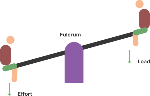
In the Class I levers, the fulcrum F is in between the effort E and the load L. Examples - handle of water pump, pliers etc.
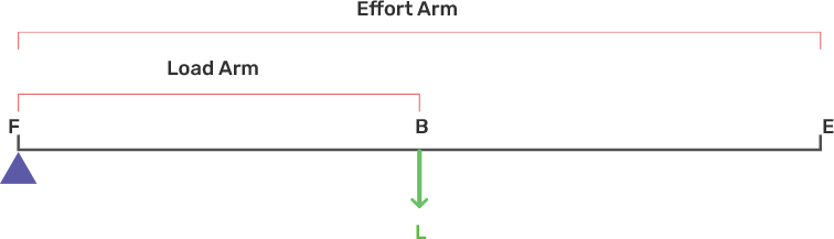
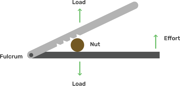
In the Class II levers, the load L is in between the effort E and the fulcrum F. so the effort arm is thus always longer than the load arm.
Example - a nutcracker, a bottle opener.
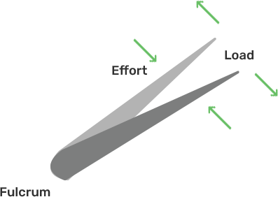
In the Class III levers, the effort E is in between the fulcrum F and the load L and the effort arm is always smaller than the load arm.
Example - sugar tongs, forearm used for lifting a load.
19. Give one example of a class I lever where mechanical advantage is
(a) More than 1,
Ans: More than one: shears used for cutting the thin metal sheets.
(b) Less than 1.
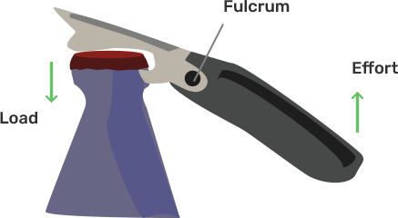
Ans: Less than one: a pair of scissors whose blades are longer than its handles.
20. What is the use of a lever if its mechanical advantage is
(a) More than 1,
Ans: If mechanical advantage is more than 1 then lever used as a force multiplier.
(b) Equal to 1
Ans: If mechanical advantage equals 1 then the lever is used as a force multiplier.
(c) Less than 1.
Ans: If mechanical advantage is less than 1 then lever is used for speed gain .
21. Both a pair of scissors and a pair of pliers belong to the same class of Levels. Name the class of lever. Which one has a mechanical advantage less than 1?
Ans: Both a pair of scissors and a pair of pliers belong to class I lever.A pair of scissors has a mechanical advantage less than 1.
22. Explain why scissors for cutting cloth may have blades longer than the handles, but shears for cutting metals have short blades and long handles.
Ans: The scissors used to cut the fabric have longer blades than the handles so that the blades go longer on the fabric than the movement of the handles.
Although shears used for cutting metal have short blades and long handles because they enable us to withstand a great deal of resistance with little effort.
23. fig. 3.12, shows a uniform metre rule of weight W is supported on a fulcrum at 60 cm mark by applying the effort E at the 90 cm mark.

(a) State with reason whether the weight W of the rule is greater than, less than or equal to effort E.
Ans: The W weight of the scale is greater than E. This is because the arm on the E side of the effort E is 30 cm and on the side the weight of the scale is 10 cm. Therefore the measurement of the W weight of the scale should be greater than the E effort.
(b) Find the mechanical advantage in an ideal case.
Ans: M.A. = effort arm / load arm =30/10 = 3
24. Which type of lever has a mechanical advantage always more than 1 ? Give reason with one example. What change can be made in this Lever to increase its mechanical advantage ?
Ans: Class II type of levers always have a mechanical advantage (M.A.) more than one.
Example: Bottle opener.
We can increase the length of the effort arm to increase its mechanical advantage.
25. Draw a diagram of a Lever which is always used as a force multiplier. How is the effort arm related to the load arm in such a Lever?
Ans: Diagram of a Lever used as a force multiplier -
In such a type of a lever the effort arm is longer than the load arm.
26. Explain why the mechanical advantage of a class II Lever is always more than 1.
Ans: In these types of levers, the load and the effort are on the same side of the fulcrum but in opposite directions and this load L is in between the effort E and the fulcrum F and the effort arm is always longer than the load arm. Therefore, M.A.>1 the mechanical advantage is always greater than 1.
In these types of levers, the load L is in between the effort E and the fulcrum F. So, the effort arm is thus always longer than the load arm. Therefore M.A>1
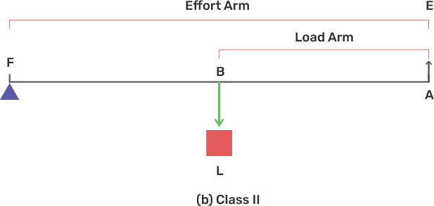
27. Draw a labeled diagram of a class II Lever. Give one example of such a Lever.
Ans: Labeled diagram of a class II Lever -
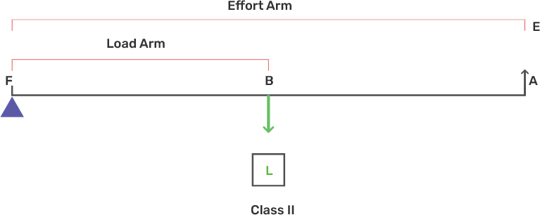
Example of a class II Lever is bottle opener
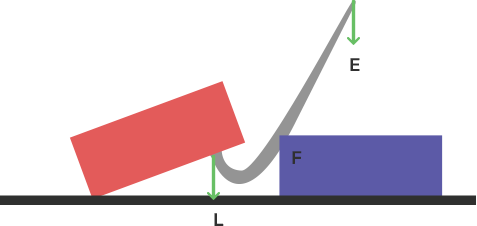
28. Fig. 3.13 shows a lemon Crusher.
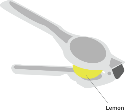
(a) In the diagram, mark the position of a fulcrum F and the line of action of load L and effort E.
Ans: Diagram of the lemon crusher -
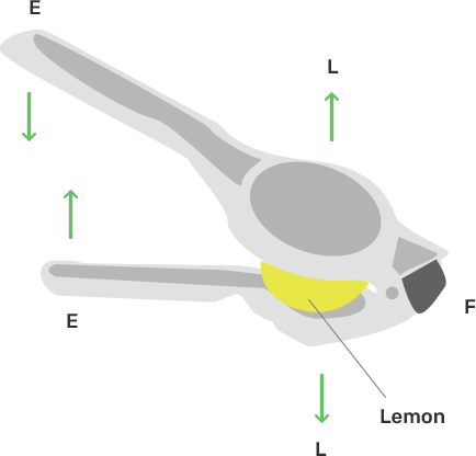
(b) Name the class of lever.
Ans: It is a class II lever.
29. The diagram below shows a road lifting a stone.
(a) Mark position of fulcrum F and draw arrows to show the direction of load L and effort E.
Ans: Complete diagram is shown below -

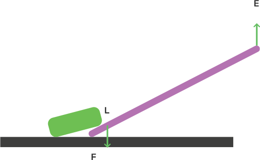
(b) What class of lever is the rod?
Ans: We can see from the diagram that the load is in between fulcrum F and effort E. therefore, this rod is a class II type lever.
(c) Give one more example of the same class of lever stated in part (b).
Ans: A nutcracker is another example of class II lever.
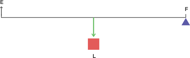
30. State the kind of liver which always has mechanical advantage less than 1. Draw a labeled diagram of such a Lever.
Ans: Class III levers always have mechanical advantage less than one.
Labeled diagram of class III Lever-
31. Explain why the mechanical advantage of class III Lever is always less than 1.
Ans:
In these types of levers, we can see from the diagram, the effort is in between the fulcrum F and the load L and so the effort arm is always smaller than the load arm. This helps by reducing the applied force (effort). Therefore M.A. < 1 and it is used as a speed multiplier.
32. Class III Levers have mechanical advantage less than 1. Why are they then used?
Ans: Class III type of levers have mechanical advantage (M.A.) less than 1 so that the arm of effort is always less than the load arm. This helps by reducing the applied force (effort). So we do not gain in force, but we gain speed, i.e. greater load shift is achieved with less effort shift.
33. Draw a labeled sketch of class III Level. Give one example of this kind of liver.
Ans: Labeled sketch of class III Level -
Example of Class III Level is foot treadle.
34. State the class of levers and the relative positions of load (L), effort (E) and fulcrum (F) in (a) A bottle opener.
Ans:
(a) A bottle opener is a II class of lever.
We can see from the above diagram of the bottle opener, the load is in between fulcrum F at one end and effort E at the other end.
(b) Sugar Tongs.
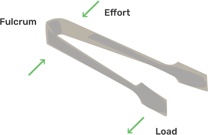
Ans: Sugar tongs is III class of lever.
We can see from the above diagram of the sugar tongs, the effort is in the middle of load L at one end and fulcrum F at the other end.
35. Draw diagrams to illustrate the position of fulcrum, load and effort in each of the following:
(a) A seesaw
Ans: all the diagrams are given below labeling with fulcrum, load and effort
A seesaw
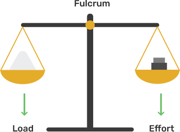
(b) a common balance
Ans:
(c) A nutcracker
Ans:
(d) Forceps
Ans:
36. Classify the following into levers as class I, class II, class III:
(a) a door
(b) a catapult
(c) claw hammer
(d) a wheelbarrow
(e) a fishing rod
(f) sugar tongs
Ans: Class I lever - (b), (c)
Class II lever - (a), (d)
Class III lever - (e), (f)
37. What type of lever is formed by a human body while (a) raising a load on a Palm.
Ans: (a) Class III type of lever.
The elbow of the human arm acts as the fulcrum. Biceps is doing effort in the middle and the load on the palm is at the other end and it is shown in the below

(b) Raising the weight of the body on toes?
Ans: Class II type of lever.
If we are raising the weight of the body on the toes then the fulcrum F is at the toes which at one end, the weight of the body acts as a load L situated in the middle and effort by muscles is at the other end which is shown in the below figure.

38. Indicate the positions of load L, effort E and fulcrum F in the forearm shown alongside in fig. 3.15. Name the class of lever.

Ans:
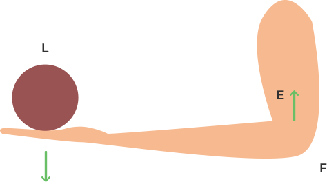
It is the III class of lever.
39. Give an example of each class of lever in the human body.
Ans:
(i) Class I lever in the action of nodding of the head or head-turning action: In this action, the spine acts as a fulcrum, the load being its front part, while the effort is its back part.
(ii) Class II lever for increasing body weight on the toes: The fulcrum is on the toes on one end, the load is medium and the muscle effort on the other side.
(iii) Class III lever for lifting arm load: The elbow joint acts as a fulcrum on one side, the biceps make an effort in the middle and the load on the palm on the other side.
40. Complete the following sentences:
(a) Mechanical advantage = ………… × velocity ratio.
Ans: Mechanical advantage = efficiency ×velocity ratio.
(b) In class II Lever, the effort arm is ………. than the lord arm.
Ans: In class II Lever, the effort arm is longer than the lord arm.
(c) A pair of scissors is a …….. Multiplayer.
Ans: A pair of scissors is a speed Multiplayer.
Multiple Choice Type -
1. Mechanical advantage (M.A.), load (L) and effort (E) are related as:
(a) M.A. = L × E
(b) M.A. × E = L
(c) E = M.A. × L
(d) none of these.
Ans: Option (b) is the correct answer.
We know that Mechanical advantage = load /effort
2. The correct relationship between mechanical advantage (M.A.), velocity ratio (V.R.) and efficiency (η) is :
(a) M.A = η × V.R
(b) V.R= η × M.A
(c) η = M.A × V.R
(d) none of these.
Ans: Option (a) is the correct answer.
We know that for an actual machine the relation between mechanical advantage and velocity ratio is -
η = (M.A.) / (V.R.)
Here η is the efficiency of the machine.
So M.A = η × V.R
3. select the incorrect statement:
(a) A machine always and efficiency less than 100 %
(b) The mechanical advantage of a machine can be less than 1.
(c) A machine can be used as a speed multiplier.
(d) A machine can have a mechanical advantage greater than its velocity ratio.
Ans: Option (d) is the correct answer.
Explanation: The mechanical advantage of a machine is always less than its velocity ratio.
4. The lever for which mechanical advantage is less than 1 has :
(a) fulcrum at the midpoint between load and effort.
(b) load between effort and fulcrum
(c) effort between fulcrum and load
(d) load and effort acting at the same point
Ans: Option (c) is the correct answer.
The lever for which mechanical advantage is less than 1 has effort between fulcrum and load.
5. Class II levers are designed to have:
(a) M.R. = V.R.
(b) M.R. > V.R.
(c) M.R. > 1
(d) M.R. < 1
Ans: Option (c) is the correct answer.
Explanation - In class II levers, the load L is in between the effort E and fulcrum F. Thus, the effort arm is always longer than the load arm and requires less effort to overcome a larger load. Therefore, M.A> 1
Numericals -
1. A crowbar of length 120 cm has its fulcrum situated at a distance of 20 cm from the load. Calculate the mechanical advantage of the crowbar.
Ans: Given Total length of a crowbar = 120 cm
Load arm = 20 cm
Effort arm = 120 – 20 = 100 cm
Mechanical advantage M.A. = Effort arm / Load arm
M.A. = 100 / 20 = 5
2. A pair of scissors has its blades 15 cm long, while its handles are 7.5 cm long. What is its mechanical advantage?
Ans: Given - Effort arm = 7.5 cm
Load arm = 15 cm
Mechanical advantage M.A = Effort arm / Load arm = 7.5 / 15 = 0.5
3. A force of 5 kgf is required to cut a metal sheet. A pair of shears used for cutting the metal sheet has its blades 5 cm long, while its handle is 10 cm long. What effort is needed to cut the sheet?
Ans: Given - Effort arm = 10 cm
Load arm = 5 cm
Mechanical advantage M.A. = Effort arm / Load arm
M.A.= 10 / 5 = 2
We know that - Effort = Load / M.A
Effort = 5 / 2 = 2.5 kgf
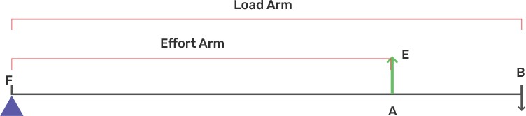
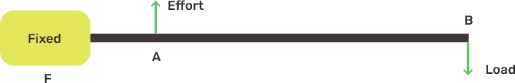
4. Fig. 3.16 below shows a lever in use.
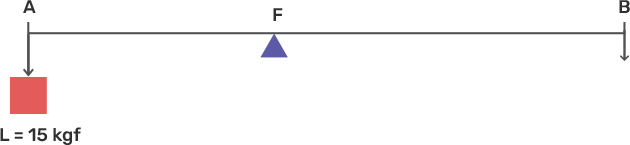
(a) To which class of lever does it belong?
Ans: This belongs to a Class I lever.
(b) If AB =1 m, AF= 0.4 m, find its mechanical advantage.
Ans: Given AB = 1m, AF = 0.4 m,
BF = 1 - 0.4 = 0.6 m
Mechanical advantage M.A = BF / AF
M.A. = 0.6 / 0.4 = 1.5
(c) Calculate the value of E.
Ans: Given Load = 15 kgf
Effort = E = Load / M.A = 15 / 1.5= 10 kgf
5. A man uses a crowbar of length 1.5 m to raise a load of 75 kgf by putting a sharp edge below the bar at a distance 1 m from his hand.
(a) Draw a diagram of the arrangement showing the fulcrum (F), load (L) and effort (E) with their directions.
Ans: Diagram of the arrangement showing the fulcrum (F), load (L) and effort (E) with their directions -
(b) State the kind of lever.
Ans: Crowbar is a class I lever
(c) Calculate:
(i) load arm,
(ii) effort arm,
(iii) mechanical advantage,
(iv) the effort needed.
Ans: Given
(i) Total length of crowbar = 1.5 m
Effort arm = 1 m
Load arm = 1.5 – 1 = 0.5 m
(ii) Effort arm = 1 m
(iii) Mechanical advantage M.A. = Effort arm / Load arm
M.A.= 1 / 0.5 = 2
(iv) The effort needed
Effort = Load / M.A.
E = 75 / 2 = 37.5 kgf
6. A pair of scissors is used to cut a piece of a cloth by keeping it at a distance 8.0 cm from its rivet and applying an effort of 10 kgf by fingers at a distance 2.0 cm from the rivet.
(a) Find: (i) the mechanical advantage of scissors and (ii) the load offered by the cloth.
Ans: Given -Effort arm = 2 cm
Load arm = 8.0 cm
Given effort = 10 kgf
(i) Mechanical advantage M.A. = Effort arm / Load arm
M.A.= 2 / 8 = 0.25
(ii) Load = M.A. × effort
= 0.25 × 10 = 2.5 kgf
(b) How does the pair of scissors act: as a force multiplier or as a speed multiplier?
Ans: As we can see that the mechanical advantage is less than 1 i.e M.A < 1 therefore, the pair of scissors acts as a speed multiplier.
7. A 4 m long rod of negligible weight is to be balanced about a point 125 cm from one end and a load of 18 kgf is suspended at a point 60 cm from the support on the shorter arm.
(a) If a weight W is placed at a distance of 250 cm from the support on the long arm, Find W.
Ans: Given - total length of rod = 4 m = 400 cm
(a) 18 kgf load is placed at 60 cm from the support. If a weight W is placed at a distance of 250 cm from the support on the long arm,
According to the principle of moments
18 × 60 = W × 250
W = 4.32 kgf
(b) If a weight of 5 kgf is kept to balance the rod, find its position.
Ans: Given W = 5 kgf
18 kgf weight is placed at 60 cm from the support.
Let 5 kg of weight be placed at d cm from the support.
According to the principle of moments -
18 × 60 = 5 × d
d = 216 cm from the support on the long arm
(c) To which class of lever does it belong?
Ans: It belongs to class I lever
8. A lever of length 9 cm has its load arm 5 cm long and the effort arm is 9 cm long.
(a) To which class does it belong?
Ans: (a) The effort arm is also more than the load arm and Length of the lever is equal to the effort arm. Therefore this is a class II lever.
(b) Draw diagram of the lever showing the position of fulcrum F and directions of both the load L and effort E.
Ans:
(c) What is the mechanical advantage and velocity ratio if the efficiency is 100%?
Ans: Mechanical advantage is ratio of effort arm to load arm.
M.A. = Effort arm / Load arm = E/L
= 9 cm / 5 cm = 1.8
M.A. = 1.8
We know that the Relation between mechanical advantage, efficiency and velocity ratio are given by formula -
M.A. = η × V.R.
(given that efficiency is 100 % so the value of η= 1)
Put the value of η -
M.A.= V.R.
V.R. = 1.8
(d) What will be the mechanical advantage and velocity ratio if the efficiency becomes 50%?
Ans: When efficiency reduces, its mechanical advantage reduces Therefore, when efficiency becomes 50%, mechanical ratio will be halved
M.A. = 1.8 / 2 = 0.9
But velocity ratio remains the same as V.R. = 1.8
9. The diagram below shows a lever in use.
(a) To which class of lever does it belong ?
Ans: It belongs to the second class of the lever.
(b) Without changing the dimensions of the lever, if the load is shifted towards the fulcrum what happens to the mechanical advantage of the lever?
Ans: If the load is shifted towards the fulcrum, the mechanical advantage of the lever will increase (M.A.>1) Without changing the dimensions of the lever.
10. Fig. 3.18 below shows a wheel barrow of mass 15 kg carrying a load of 30 kgf with its centre of gravity at A. The points B and C are the centre of wheel and tip of the handle such that the horizontal distance AB = 20 cm and AC = 40 cm.
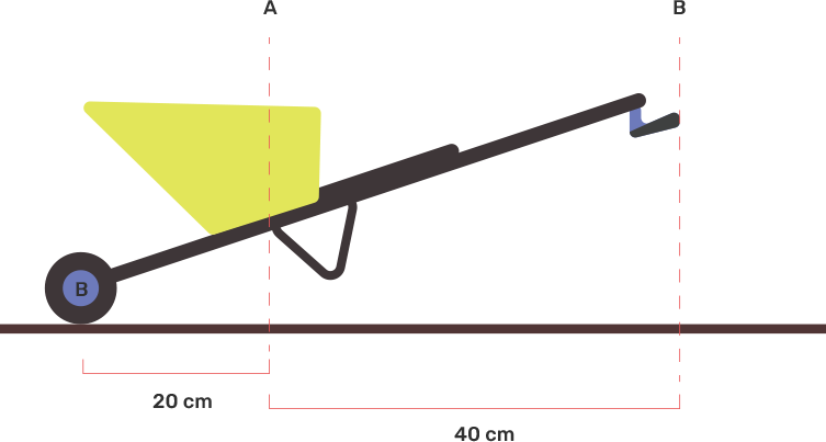
Find: (a) The load arm,
Ans: Load arm AF = 20 cm
(b) The effort arm,
Ans: Effort arm CF = 60 cm
(c) The mechanical advantage,
Ans: Mechanical advantage M.A. = CF / AF
M.A. = effort arm / load arm= 60 / 20 = 3
(d) The minimum effort required to keep the leg just off the ground.
Ans: Total load = 30 + 15 = 45 kgf
Effort = Load / M.A = (30 + 15) / 3 = 15 kgf
Minimum effort required to keep the leg just off the ground will be 15 kgf.
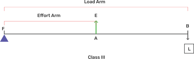
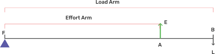
11. Fig. 3.19 below shows the use of a lever.
(a) State the principle of moments as applied to the above lever.
Ans: (a) According to the principle of moments we know that -
Moment of the load about the fulcrum is equal to the moment of the effort about the fulcrum so from the diagram -
load × FB = Effort × FA
(b) To which class of lever does it belong? Give an example of this class of lever.
Ans: It belongs to Class III lever. The example of this lever is a knife.
(c) If FA = 10 cm, AB = 490 cm, calculate:
(i) the mechanical advantage
Ans: Given FA = 10 cm
AB = 490 cm
BF = 490 + 10 = 500 cm
The mechanical advantage will be -
M.A = AF / BF
M.A. = 10 / 500 = 1/50
(c)(ii) the minimum effort required to lift the load (= 50N).
Ans: The minimum effort required to lift the load will be by formula -
Effort = Load / M.A
= 50 / (1 / 50)
= 50 × 50 = 2500 N
12. A fire tongs has its arms 20 cm long. It is used to lift a coal of weight 1.5 kgf by applying an effort at a distance 15 cm from the fulcrum.
Find: (i) the mechanical advantage of fire tongs
Ans: Given - Fire tongs has its arms = 20 cm
Effort arm = 15 cm
Load arm = 20 cm
Mechanical advantage M.A.by below formula -
M.A. = Effort arm / Load arm
M.A. = 15 / 20 = 0.75
(ii) the effort needed.
Ans: Effort = Load / M.A
E = 1.5 / 0.75 = 2.0 kgf
Effort needed will be 2 kgf.
Exercise - 3(B)
1. What is a fixed pulley? State its one use.
Ans: A pulley which has stationary rotation of the axis is called a fixed pulley.
This type of pulley is used to lift a small load such as a bucket of water.
2. What is the ideal mechanical advantage of a single fixed pulley? Can it be used as a force multiplier?
Ans: The mechanical advantage of a single fixed pulley is 1. No, it cannot be used as a force multiplier.
3. Name the pulley which has no gain in mechanical advantage. Explain, why is such a pulley is then used?
Ans: In a single fixed pulley, there is no gain in mechanical gain.
A single pulley is only used to change the direction of the effort to be used i.e. by its use the effort can be used in a very simple way and in a particular convenient direction. It is difficult to lift the load upward directly .
4. What is the velocity ratio of a single fixed pulley?
Ans: The velocity ratio of a single fixed pulley is one.
5. In a single fixed pulley, if the effort moves by a distance x downwards, by what height is the load raised upwards?
Ans: In a single fixed pulley, if the effort moves by a distance x downwards, the load rises with the distance x upwards.
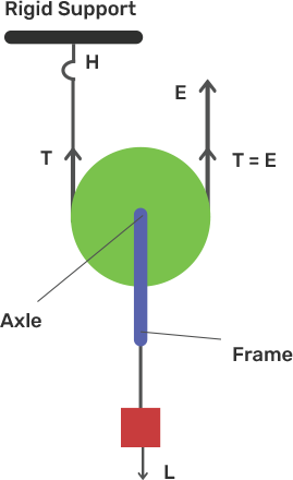
6. What is a single movable pulley? What is its mechanical advantage in the ideal case?
Ans: A single movable pulley which has a movable axis of rotation is called a single movable pulley. It does not have a fixed axis of rotation.
The mechanical advantage of a single movable fixed pulley in the ideal case is 2.
7. Name the type of single pulley that has an ideal mechanical advantage equal to 2. Draw a labeled diagram of the pulley mentioned by you.
Ans: The single movable pulley has an ideal mechanical advantage equal to 2 and acts as a force multiplier.
8. Give two reasons why the efficiency of a single movable pulley system is not 100%.
Ans: Due to the following reasons the efficiency of a single movable pulley system is not 100 percent and they are given below -
(i) It has non zero friction because of pulley bearing.
(ii) The weight of the pulley and string/ rope is not zero.
9. In which direction the force needs to be applied, when a single pulley is used with a mechanical advantage greater than 1? How can you change the direction of force applied without altering its mechanical advantage? Draw a labelled diagram of the system.
Ans: We need to apply the force in an upward direction.
With the help of a single movable pulley and a fixed pulley along with, we can change the direction of the applied force without changing its mechanical advantage (M.A.)

10. What is the velocity ratio of a single movable pulley? How does the friction in the pulley bearing affect it?
Ans: A single movable pulley always has the velocity ratio 2.
There is no effect of friction on the pulley.
11. In a single movable pulley, if the effort moves by a distance x upwards, by what height is the load raised?
Ans: If the effort moves by a distance x upwards then the load is raised to a height of x /2.
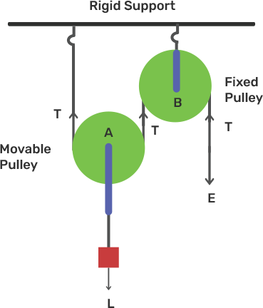
12. Draw a labeled diagram of an arrangement of two pulleys, one fixed and other moveable. In the diagram, mark the directions of all forces acting on it. What is the ideal mechanical advantage of the system? How can it be achieved?
Ans: Diagram of an arrangement of two pulleys, one fixed and other movable pulley is shown in below -
The system has 2 ideal mechanical advantages.
By assuming that the string and the pulley have no mass and also there is no friction in the pulley bearings between the string and surface of the rim of the pulley, we can achieve this.
13. The diagram alongside shows a pulley arrangement.
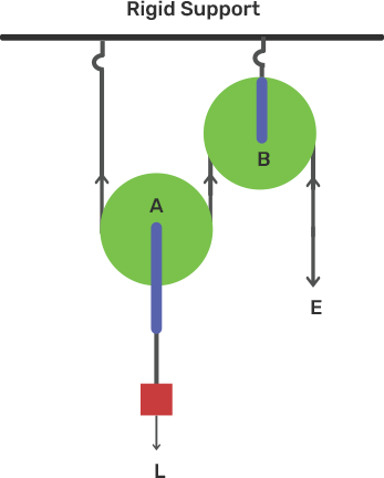
(a) Name the pulleys A and B.
Ans: Pulley A is movable and pulley B is fixed.
(b) In the diagram, mark the direction of tension on each strand of string.
Ans:
(c) What is the purpose of pulley B?
Ans: The purpose of pulley B ( fixed pulley) is to change the direction of effort E.
(d) If the tension is T, deduce the relation between (i) T and E, and (ii) E and L.
Ans: If the tension is T then (i) Relation between Tension T and effort E will be -
E = T
In the system at the free end, the effort E balances the force tension T.
So, Effort E = Tension T
(e) What is the velocity ratio of the arrangement?
Ans: The velocity ratio (V.R.) of this arrangement is two.
(f) Assuming that the efficiency of the system is 100%, what is the mechanical advantage?
Ans: The mechanical advantage is 2, if the efficiency of the system is 100%.
14. State four differences between a single fixed pulley and a single movable pulley.
Ans:
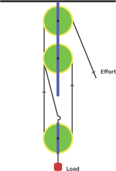
15. The diagram alongside shows and arrangement of three pulleys A, B and C. The load is marked as L and the effort as E.
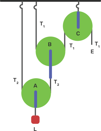
(a) Name the pulleys A, B and C.
Ans: Pulleys A and pulley B - movable pulleys
Pulley C - fixed pulley.
(b) Mark in the diagram the direction of load (L), effort (E) and tension T1 and T2 in the two strings.
Ans:

(c) How are the magnitudes of L and E related to the tension T1 ?
Ans: The magnitude of effort = E = T1 and
The magnitude of Lord = L = 22 T1
L= 4T1
(d) Calculate the mechanical advantage and velocity ratio of the arrangement.
Ans: The mechanical advantage = (M.A.) = 22 = 4 and
The velocity ratio = (V.R.) = 22 = 4
(e) What assumptions have you made in parts (c) and (d)?
Ans: We have made an assumption in parts (c) and (d) that the pulleys A and B are weightless and there is no friction.
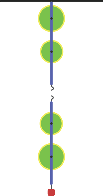
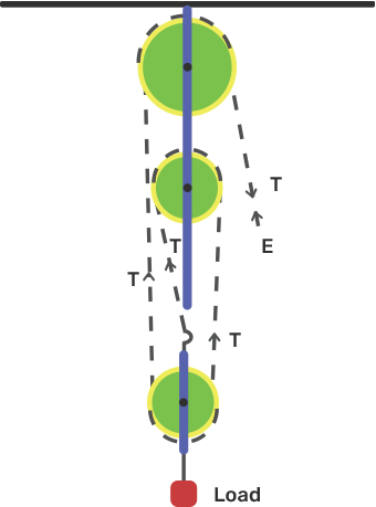
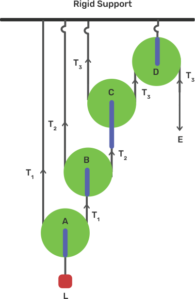
16. Draw a diagram of a combination of three movable pulleys and one fixed pulley to lift up a load. in the diagram, show the directions of load, effort and tension in each strand. Find: (i) the mechanical advantage.
Ans: Diagram of combination of three movable pulleys and one fixed pulley -
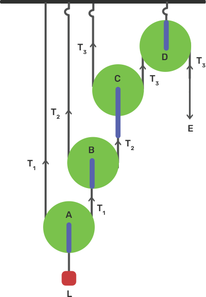
Tension ${{T}_{1}}$ in the string that passes over the pulley A can be given as,
$2{{T}_{2\text{ }}}=\text{ }{{\text{T}}_{1}}$
${{T}_{1}}\text{ = L/2}$
Now the tension ${{T}_{2}}$ in the string that passes over the pulley B can be given as,
$2{{T}_{2}}\text{ = }{{\text{T}}_{1}}$
${{T}_{2}}\text{ = }{{\text{T}}_{1}}/2\text{ = L/}{{\text{2}}^{2}}$
Now the tension ${{T}_{3}}$ in the string that passes over the pulley C can be given as,
$2{{T}_{3}}\text{ = }{{\text{T}}_{2}}$
${{T}_{3}}\text{ = }{{\text{T}}_{2}}/2\text{ = L/}{{\text{2}}^{3}}$
At equilibrium, ${{T}_{3\text{ }}}=\text{ E}$
Hence, $E\text{ = L/}{{\text{2}}^{3}}$
(i) Mechanical Advantage, $M.A\text{ = L/E = }{{\text{2}}^{3}}$
(ii) Find velocity ratio.
Ans: As one end of each string passing over a movable pulley is fixed. So, the other end of the string moves up twice the distance moved by the axle of the movable pulley. If the load L moves up by a distance x then ${{d}_{L\text{ }}}=\text{ x}$ and effort moved by a distance ${{2}^{3}}x\text{ or }{{\text{d}}_{E}}\text{ = }{{\text{2}}^{3}}x$. Hence the velocity ratio (V.R) is given as,
$V.R\text{ = (Distance moved by effort }{{\text{d}}_{E}})/(Dis\tan ce\text{ moved by load }{{\text{d}}_{L}})$$V.R\text{ = (}{{\text{2}}^{3}}x)/x\text{ = }{{\text{2}}^{3}}$
(iii) Find the efficiency of the combination in ideal situations.
Ans: Efficiency = $M.A/V.R\text{ = }{{\text{2}}^{3}}/{{2}^{3}}\text{ = 1 or 100}$%
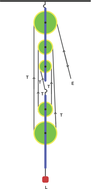
17. Draw a diagram of a block and tackle system of pulleys having a velocity ratio of 5. In your diagram indicate clearly the points of application and the directions of the load L and effort E. Also mark the tension T in each strand.
Ans:
18. Give reasons for the following:
(a) In a single fixed pulley, the velocity ratio is always more than the mechanical advantage.
Ans: In order to overcome the friction between the strings and grooves of the pulley some efforts are wasted in case of a single fixed pulley. Therefore, the effort needed should be greater than the load and thus the velocity ratio is always greater than the mechanical advantage.
(b) The efficiency of a movable pulley is always less than 100%.
Ans: As efforts are wasted in overcoming the friction between the strings and grooves of the pulley therefore the efficiency of a movable pulley is always less than 100 %.
(c) In the case of a block and tackle system, the mechanical advantage increases with the increase in the number of pulleys.
Ans: As the mechanical advantage is equal to the total number of pulleys in both the blocks therefore it increases with increase in number of pulleys.
(d) The lower block of a block and tackle pulley system must be of negligible weight.
Ans: As the efficiency depends upon the mass of the lower block therefore efficiency is reduced due to the weight of the lower blocks of pulleys.
19. Name a machine which is used to:
(a) Multiply force
Ans: Multiple force - a movable pulley is used
(b) Multiply speed
Ans: Multiply speed - Class III lever
(c) Change the direction of force applied.
Ans: Change the direction of force applied - Single fixed pulley
20. State whether the following statements are true or false by writing T and F.
(a) The velocity ratio of a single fixed pulley is always more than 1.
Ans: False
(b) The velocity ratio of a single movable pulley is always 2.
Ans: True
(c) The velocity ratio of a combination of n movable pulleys with a fixed pulley is always 2n.
Ans: True
(d) The velocity ratio of a block and tackle system is always equal to the number of strands of the tackle supporting the load.
Ans: True
Multiple Choice Type -
1. A single fixed pulley is used because it:
(a) Has a mechanical advantage greater than 1
(b) Has a velocity ratio less than 1
(c) Gives 100% efficiency
(d) Helps to apply the effort in a convenient direction.
Ans: Option (d) is the correct answer.
A single fixed pulley is used to apply the effort in a convenient direction.
2. The mechanical advantage of an ideal single movable pulley is:
(a) 1
(b) 2
(c) less than 2
(d) less than 1.
Ans: Option (b) is the correct answer.
The mechanical advantage of an ideal single movable pulley is two.
3. A movable pulley is used as :
(a) A force multiplier
(b) A speed multiplier
(c) A device to change the direction of effort
(d) An energy multiplier
Ans: Option (a) is the correct answer.
A movable pulley is used as a force multiplier.
In the case of a movable pulley we can lift the load by applying an effort equal to half the load. So it is used as a force multiplier.
Numericals -
1. A woman draws water from a well using a fixed pulley. The mass of the bucket and water together is 6 kg. The force applied by the woman is 70 N. Calculate the mechanical advantage. (Take g = $10m/{{s}^{2}})$
Ans: According to the question,
The force applied by the woman = 70 N
The mass of the bucket and water together = 6 kg
Total load = 6 × 10 = 60 N
Mechanical Advantage, M.A = load / effort
M.A = 60/70 = 0.857
2. A fixed pulley is driven by a 100 kg mass falling at a rate of 8.0 m in 4.0 s. It lifts a load of 75.0 kgf. Calculate:
(a) The power input to the pulley taking the force of gravity on 1kg as 10 N.
Ans: Effort driving the pulley is,
$E = mg = 100 \times 10 = 1000\,N$
The velocity of falling (v) = 8.0m/4.0s = 2 m/s
Input power is, ${{P}_{in\text{ }}}=\text{ E }\!\!\times\!\!\text{ v = 1000 }\!\!\times\!\!\text{ 2 = 2000 W}$
(b) The efficiency of the pulley
Ans: Load on the pulley is,
$L = 75 \times 10 = 750\,N$
Hence mechanical advantage is,
M.A = L/E = 750/1000 = 0.75
When the effort moves by a distance x downward then the load moves by the same distance in upward direction. Thus,
V.R = 1
Therefore the efficiency is,
$\eta \text{ }$ = M.A/V.R = 0.75/1 = 0.75 or 75%
(c) the height to which the load is raised in 4.0 s.
Ans: The height to which load is raised in 4s is 8m because load moves by the same
distance upwards when the effort moves by a distance x downwards.
3. A single fixed pulley and a movable pulley both are separately used to lift a load of 50 kgf to the same height. Compare the efforts applied.
Ans: The effort $({{E}_{f}})$needed to lift a load should be equal to the load itself in case of a single fixed pulley. Hence,
${{E}_{f}}\text{ = L}$
In case of a movable pulley the effort $({{E}_{m}})$ needed to lift a load equal to half of the load. Hence,
${{E}_{m}}\text{ = 50 kgf/2 = 25kgf}$
Therefore the ratio of effort applied by respective pulley is,
${{E}_{f}}/{{E}_{m}}\text{ = 2/1}$
4. In a block and tackle system consisting of 3 pulleys, a load of 75 kgf is raised with an effort of 25 kgf. Find: (i) Mechanical advantage
Ans: According to the question,
Load = 75 kgf
Effort = 25 kgf
Number of pulleys, n = 3
M.A = Load / Effort = 75/25 = 3
(ii) Find the velocity ratio.
Ans: Velocity ratio, V.R = n = 3
(iii) Find the efficiency.
Ans: Efficiency = M.A / V.R = 3/3 = 1 or 100%
5. A block and tackle system has 5 pulleys. If an effort of 1000 N is needed in the downward direction to raise a load of 4500 N, calculate:
(a) The mechanical advantage,
Ans: According to the question, a block and tackle system has 5 pulleys so n = 5.
Effort = 1000 N
Load = 4500 N
The mechanical advantage is,
M.A = Load / Effort = 4500/1000 = 4.5
(b) Calculate the velocity ratio
Ans: The velocity ratio = n = 5
(c) The efficiency of the system.
Ans: Efficiency of the system = M.A / V.R = 4.5/5 = 0.9 or 90%
6. In the figure, draw a tackle to lift the load by applying the force in downward direction.
(a) Mark in the diagram the direction of load L and effort E.
Ans: (a)

(b) If the load is raised by 1m, through what distance will the effort move?
Ans: If the load is raised by 1m then effort move = 1 × 5 = 5m
(c) State how many strands of tackle are supporting the load.
Ans: Five strands of tackle are supporting the load.
(d) What is the mechanical advantage of the system ?
Ans: Mechanical advantage of the system is given by,
M.A = Load / Effort = 5T/T = 5
7. A pulley system has a velocity ratio 3. Draw a diagram showing the point of application and direction of load(L), effort (E) and tension (T). It lifts a load of 150 N by an effort of 60 N. Calculate the mechanical advantage. Is the pulley system ideal ? Give a reason.
Ans:

According to the question,
Load = 150 N
Effort = 60 N
Mechanical Advantage = Load / Effort = 150/60 = 2.5
The pulley system is not ideal because the mechanical advantage is less than 3.
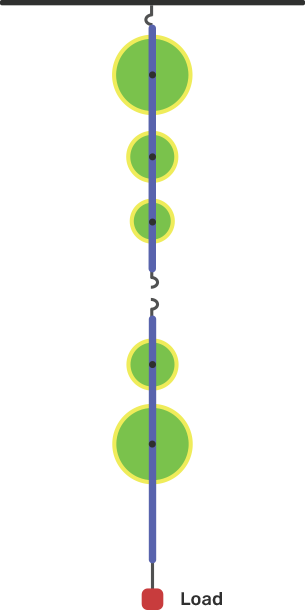
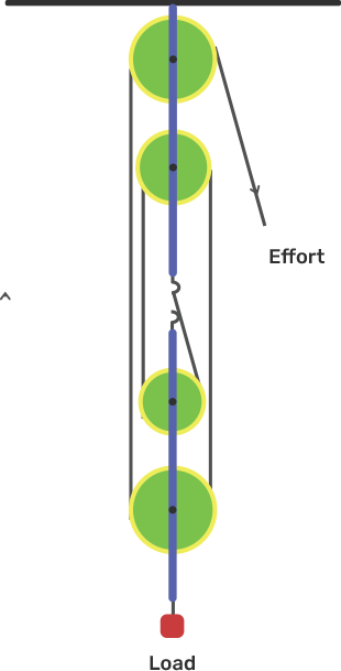
8. Figure shows a system of four pulleys. The upper two pulleys are fixed and lower two are movable.
(a) Draw a string around the pulleys. Also show the point of application and direction in which the effort E is applied.
Ans:
(b) What is the velocity ratio of the system?
Ans: Velocity ratio of the system = n = 4
(c) How are effort and load of the pulley system related?
Ans: The relation between load and effort is,
M.A = Load / Effort = n = 4
Load = 4 ×Effort
(d) What assumption do you make in arriving at your answer in part (c)?
Ans: The assumption we made are;
(i) There is no friction in the pulley bearings.
(ii) The weight of the lower pulley is negligible.
(iii) The effort is applied downward.
9. Figure shows a block and tackle system of pulleys used to lift a load.
(a) How many strands of tackle are supporting the load?
Ans: (a) There are four strands of tackle supporting the load.
(b) Draw the arrows to represent tension T in each strand.
Ans:
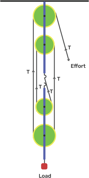
(c) What is the mechanical advantage of the system?
Ans: The mechanical advantage of the system is,
M.A = Load / Effort = 4T/T = 4
(d) When the load is pulled up by a distance of 1m, how far does the effort end?
Ans: When the load is moved up by a distance of 1m then the effort ends up moving by a distance of 1 × 4 = 4m.
(e) How much effort is needed to lift a load of 100 N?
Ans: M.A = Load / Effort
4 = 100/ Effort
Effort = 100/4 = 25 N
10. A block and tackle system has the velocity ratio 3. Draw a labeled diagram of the system indicating the points of application and the direction of load L and E. A man can exert a pull of 200 kgf.
(a) What is the maximum load he can raise with this pulley system if its efficiency is 60 %?
Ans: According to the question, a block and tackle system has the velocity ratio (V.R) = 3.
Therefore, the number of pulleys (n) = 3
The diagram is shown below as,
The effort put by man is E = 200 kgf
Efficiency, ƞ = 60 %
\[\eta \] = 1 – w/nE
0.6 = 1 – w/(3 × 200)
w/600 = 1 – 0.6
Thus, w = 0.4 × 600 = 240kgf
Hence, load is
L = nE – w = 600 – 240 = 360kgf
(b) If the effort end moves a distance of 60cm, what distance does the load move?
Ans: The velocity ratio of the system is 3. Therefore, we got
V.R = ${{d}_{E}}/{{d}_{L}}\text{ = n = 3}$
Therefore, ${{d}_{L}}\text{ = }{{\text{d}}_{E}}/3\text{ = 60/3 = 20cm}$
11. You are given four pulleys and three strings. Draw a neat and labelled diagram to use them so as to obtain maximum mechanical advantage equal to 8. In your diagram mark the direction of load L, effort E and tension in each strand. What assumptions have you made to obtain the required mechanical advantage?
Ans:
Assumptions that are made;
(i) There is no friction in the pulley bearing.
(ii) The pulleys and the string are massless.


FAQs on Machines Solutions for ICSE Board Class 10 Physics
1. What do you understand about a simple machine? State the principle of a machine which is ideal.
A machine is a tool by which we can overcome a great deal of resistance (or loading) at a certain time by using a little force (or effort) in the right place and in the way we want or where we can get profit quickly. An ideal machine is a machine where the energy supplied as an output is equal to the input power. The goal of an ideal machine is to turn all the given energy into useful power, i.e., 100% efficient. This means that all the input energy is converted into the required output energy.
2. Name the machine for each of the following uses:
(a) To increase power - Power repellent: a jack is used to lift a car
(b) To change the point of use of the power - Switching power supply: The rotation wheel is rotated with the help of a chain by attaching power to the pedal.
(c) To change the direction of power - Changing the direction of force: lifting a bucket full of water from a well, a single pulley is used by placing the pressure on the ground instead of pointing it up when the bucket is lifted without using a pool.
(d) to accelerate the gain in speed - when the scissors are used to cut the fabric, the swords of the scissors move longer over the fabric while its handles move slightly.
3. Define the efficiency of the machine. Give two reasons why the machine is not 100% working properly?
The term machine efficiency is defined as the average of the work performed on a machine and the work performed on a machine by effort or efficiency is a measure of the output and input function. If a machine is functioning properly then it means that it is 100% efficient. This is because of a decrease in strength due to the collision with the weight of the moving parts in the operating machinery. Thus, the output power is less than the input power.
4. When does the machine operate (a) as a power multiplier and (b) a multiplier of speed? Can the machine work as a power multiplier and a speed multiplier at the same time?
(a) If the effort arm is longer than the load arm where the machine operates as a power multiplier. The mechanical advantage of such equipment is greater than 1.
(b) If the test arm is shorter than the load arm the machine acts as a speedometer. The mechanical advantage of such equipment is less than 1.
Energy-efficient machines cannot gain speed and vice versa. Therefore, it is not possible for a machine to function as a power multiplier and a speed multiplier at the same time.
5. Name four ways in which machines are useful to us?
A machine is a tool by which we can overcome a great deal of resistance (or loading) at a certain time by using a little force (or effort) in the right place and in the way we want or where we can get profit quickly. A machine is useful to us in the following ways:
(a) Turning the point of effort into a positive point.
(b) Lifting a heavy load with minimal effort.
(c) Changing the direction of the effort into a positive direction.
(d) For rapid profit.