


Science Notes for Chapter 10 Human Eye and Colourful World Class 10 - FREE PDF Download
Vedantu provides Revision notes for class 10 science chapter 10, a key resource for students who want to navigate the concepts of Science at the 10th-grade level. Students will learn about the concepts related to this chapter, such as the power of accommodation, defects of vision, refraction of light, Atmospheric refraction, scattering of light, etc.
 Table of Content
Our FREE PDF download of the Class 10 Science Revision Notes allows you to quickly access and review the chapter content. For a comprehensive study experience, check out the FREE PDF here and refer to the CBSE Class 10 Science Syllabus for detailed coverage. Vedantu's notes offer a focused, student-friendly approach, setting them apart from other resources and providing you with the best tools for success.
CBSE Notes Class 10 Science Chapter 10 - Human Eye and Colourful World - 2026-27
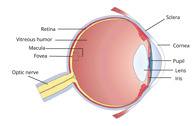
Cornea: Transparent membrane covering the front of the eye; allows light to enter.
Aqueous Humour: Fluid behind the cornea.
Iris: Dark-colored, muscular diaphragm behind the cornea with a central opening called the pupil; controls light entry by adjusting the pupil size.
Pupil: Black due to no light reflection; size regulated by the iris.
Lens: Convex lens made of a transparent, jelly-like material; changes curvature and focal length with the help of ciliary muscles.
Ciliary Muscles: Hold the lens in place and adjust its curvature for focusing.
Retina: Light-sensitive membrane at the back of the eye; contains rods and cone cells that send electrical signals to the brain via the optic nerve.
Vitreous Humour: Fluid filling the space between the retina and the lens.
Image Formation: Light is focused by the lens to form an inverted image on the retina; signals are sent to the brain for image interpretation.
Accommodation: Ability of the eye to focus on objects at varying distances.
Range of Vision: Distance between the near point and far point of vision.
Color Vision: Cone cells in the retina detect colors in bright light; rod cells function in low light but don’t distinguish colors.
Defects of Eye
Colour Blindness: Difficulty in distinguishing between certain colours, often due to genetic factors. It arises when cone cells in the eye have reduced or absent pigments for red, green, or blue light.
Nyctalopia (Night Blindness): Inability to see in low light; can be congenital, due to injury, malnutrition, or Vitamin A deficiency. It involves issues with rod cells in the retina that are responsible for low-light vision.
Cataract: Clouding of the eye's crystalline lens, leading to decreased vision and yellowing of the lens. Causes include UV rays, radiation, and protein denaturation, which affect color perception and vision clarity.
Hypermetropia (Farsightedness): Difficulty seeing close objects clearly while distant vision remains clear. Light rays focus behind the retina rather than on it.
Myopia (Nearsightedness): Difficulty seeing distant objects clearly. Light rays focus in front of the retina, causing clear near vision but blurry distance vision.
Astigmatism: Distorted vision caused by light rays not meeting at a common focus. It can result in blurred vision for both near and far objects and may accompany hypermetropia or myopia.
Presbyopia: Age-related condition where the lens becomes hard, making it difficult to focus on close objects. Common in individuals over 50 and can affect those with myopia.
Important Topics of Class 10 Chapter 10 Human Eye and the Colourful World
Importance of Revision Notes for Class 10 Chapter 10 Human Eye and Colourful World
After analysing the human eye class 10 Revision Notes, students can design their study material in a well-structured way. They get new ideas to shape their study materials.
The human eye and the colourful world notes are comprehensive and prepared by Science experts.
It covers a thorough explanation of the human eye parts and its structural depiction.
It also emphasises the understanding of the human eye working along with different functions performed by the human eye.
Tips for Learning the Class 10 Science Chapter 10 Human Eye and the Colourful World
Focus on core processes with illustrations and examples.
Draw and label diagrams for clarity.
Create brief summaries of each process.
Connect concepts to everyday examples.
Solve past exam questions to test understanding.
Explain concepts to others to reinforce learning.
Revisit material frequently to retain information.
Utilise platforms like Vedantu for additional support.
Conclusion
Class 10 science Chapter 10 Revision notes by Vedantu are designed with the main aim of helping students focus on the chapter's important concepts. Every concept is explained briefly and in an easy-to-understand language to help students improve their conceptual knowledge. The Notes also contain various shortcut techniques which can be used to remember the concepts effectively.
Related Study Materials for Class 10 Science Chapter 10 Human Eye and the Colourful World
Revision Notes Links for Class 10 Science Chapter 10
You can also access chapter-wise Revision Notes for Class 10 Science from the links below and kick-start your preparation for Class 10 Board exams.
Important Study Materials for Class 10 Science
FAQs on CBSE Notes Class 10 Science Chapter 10 - Human Eye and Colourful World - 2026-27
1. What are the key points to remember in the Human Eye and Colourful World for quick revision?
For revision of Class 10 Science Chapter 10, focus on the structure of the eye, major functions (like accommodation and image formation), common vision defects, how light is refracted through a prism, atmospheric refraction effects (such as twinkling of stars and advanced sunrise), and the reasons behind the scattering of light (blue sky, red sunrises and sunsets). Summarising these core ideas helps reinforce the chapter’s key concepts.
2. How does the human eye adjust to view objects at different distances? (Revision summary)
The human eye adjusts its lens shape (curvature) with the help of ciliary muscles — a process called accommodation. This allows the eye to focus light on the retina for clear vision of both near and distant objects within a certain range, called the range of vision.
3. What are the main types of vision defects covered in Human Eye and Colourful World Class 10 notes?
The main vision defects include Myopia (nearsightedness), Hypermetropia (farsightedness), Astigmatism, Presbyopia (age-related), Cataract, and Colour Blindness. Each has specific causes and correction methods, such as using lenses or surgery.
4. What is the significance of atmospheric refraction in daily life?
Atmospheric refraction explains phenomena like the twinkling of stars, the visible sun before actual sunrise, and delayed sunsets. These effects happen because light bends as it passes through layers of the atmosphere with varying densities.
5. How does dispersion of white light by a prism help in understanding the colourful world?
Dispersion by a glass prism splits white light into its seven constituent colours, forming a spectrum. This explains natural phenomena like the formation of rainbows and demonstrates that white light is made up of multiple colours.
6. Why does the sky appear blue and sunsets appear red? (Concept summary)
The blue colour of the sky results from the scattering of shorter blue wavelengths by air molecules, while red sunsets occur because only longer red wavelengths reach our eyes when the sun is near the horizon, as other colours are more scattered.
7. What revision strategies can help score better in the Human Eye and Colourful World chapter?
For effective revision:
- Draw and label diagrams of the eye and refraction processes
- Create short notes on each key process (refraction, accommodation, defects)
- Review commonly confused concepts (e.g., myopia vs hypermetropia)
- Practice with past exam questions and summaries
- Explain the concepts to peers or use flashcards for self-testing
8. How does understanding the chapter as a concept map improve revision?
Creating a concept map connects major chapter themes visually — like the flow from the structure of the eye to vision processes, defects, light phenomena, and their atmospheric/real-world applications. This improves memory and helps spot interrelations quickly during revision.
9. Why is revising the Human Eye and Colourful World chapter important for board exam preparation?
This chapter is fundamental because it builds the foundation for light and optics, includes regularly tested phenomena, and develops reasoning skills useful for physics and biology. A good revision ensures students can attempt different question types confidently in the CBSE board exams.
10. What misconceptions should students avoid while revising this chapter?
Common misconceptions include confusing the correction methods for myopia and hypermetropia, thinking the eye forms an erect image, and assuming all colour vision issues are inherited. Careful reading of revision notes helps clarify and avoid these errors.