


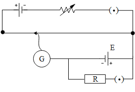
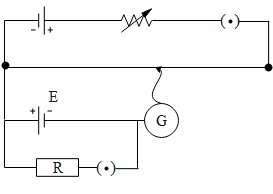
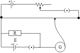
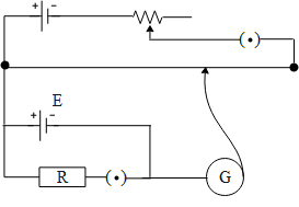
The correct circuit for the determination of internal resistance of a battery using potentiometer is:
A.
B.
C.
D.
Answer
591.6k+ views
Hint: When using a potentiometer there are certain things to be kept in mind so that we are in a position of using it. The battery used in the potentiometer should have an emf greater than that of the battery whose internal resistance is to be determined. The two batteries should be connected in such a way, that the polarities of either of them are having the same direction i.e. the negative should be connected across the negative terminal and the positive terminal with the positive terminal across the potentiometer wire. A key should be connected in series with the resistance, which is to be connected parallel. If all these conditions are satisfied then we are ready to use the potentiometer.
Complete step by step answer:
The potentiometer works on the principle of potential gradient. When a battery is connected to the potentiometer, the galvanometer shows no deflection when the potential gradient across the length of the wire becomes equal to the emf of the battery connected to the potentiometer whose internal resistance is to be determined. To begin with determining the internal resistance of the battery we connect an external resistance in parallel to the battery with the key. This is done so that the first we can determine the emf of the battery using the potentiometer by keeping the key open. Hence the battery whose emf is to be determined gives no current. Further we plug the key in, a result of which the battery delivers the current across the internal as well as the external resistance. Hence we calculate the balancing length for this condition. Further we determine the internal resistance of the battery by taking the ratio of the two balancing points. Now that we have understood how a potentiometer works let us verify the above circuit diagrams. If we consider the option A and b the batteries whose internal resistance is to be determined are connected in opposite polarities. Hence option A and B are incorrect. Further if we consider option C, the key is connected in series with the battery instead of the external resistance. Therefore option C is also incorrect. In option D, the batteries are connected with the same direction across the potentiometer wire as well as the key is connected in series with the external resistance.
Hence the correct answer of the above question is option D.
Note:
It is also to be noted that the emf of the battery whose external resistance is to be determined should always have an emf less than that of the battery of the potentiometer. If this condition is not satisfied, Then the potential gradient generated will have no balanced point across the total length of the potentiometer wire. Hence if we place the needle along any length of the wire the galvanometer will always display a deflection.
Recently Updated Pages
In a plane electromagnetic wave the electric field class 12 physics CBSE
A plane electromagnetic wave travels in vacuum along class 12 physics CBSE
Basicity of sulphurous acid and sulphuric acid are
The magnetic field in a plane electromagnetic wave class 11 physics CBSE
Master Class 12 English: Engaging Questions & Answers for Success
Master Class 12 Social Science: Engaging Questions & Answers for Success
Trending doubts
Which are the Top 10 Largest Countries of the World?
Draw a labelled sketch of the human eye class 12 physics CBSE
Which state in the country is at the forefront in controlling class 12 social science CBSE
Mention the role of cyanobacteria as a biofertiliz class 12 biology ICSE
Where is the largest hydroelectric power station located class 12 biology CBSE
Which country did Danny Casey play for class 12 english CBSE