


What is an operational amplifier? Explain its working as a non-inverting amplifier.
Answer
597.6k+ views
Hint: An operational amplifier is a linear Integrated Circuit having multiple ends or terminals. This device basically amplifies. A non-inverting amplifier is an operational amplifier circuit configuration which produces an amplified output signal. The output signal and the input signal of the non-inverting are in phase.
Formula used:
\[{{A}_{CL}}~=\text{ }\dfrac{{{V}_{OUT}}\text{ }}{{{V}_{IN}}}\]
Complete answer:
An operational amplifier is a linear Integrated Circuit having multiple ends or terminals. Operation Amplifier is often abbreviated as an op-amp. This device basically amplifies the voltage. A non-inverting amplifier is an operational amplifier circuit configuration which produces an amplified output signal. The output signal and the input signal of the non-inverting are in phase.
Let us understand its working by the following diagram.
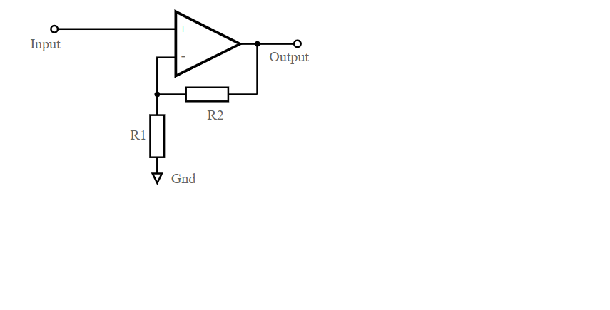
It can be seen from the diagram that the output voltage is divided across resistors R1 and R2 before it is applied to the inverting input. The non-inverting input is grounded so \[{{V}_{in}}=0\]. As the inverting input end is at ground level, the junction of the resistors R1 and R2 must also be at ground level. This means that the voltage drop across R2 will be zero. So, the current flowing through R1 and R2 must be zero. Thus, the voltage drops across R1 is zero, and therefore the output voltage and the input voltage will be equal, which is 0V.
When a positive input signal is applied then there will be a shift in the output voltage to keep the inverting input terminal and the input voltage applied equal. This means
\[{{V}_{R2}}={{V}_{in}}={{I}_{2}}{{R}_{2}}\], \[{{I}_{2}}\] is the current flowing at the junction of R1 and R2
\[{{V}_{out}}={{I}_{2}}~({{R}_{1}}~+\text{ }{{R}_{2}})\]
The voltage gain of the closed-loop will be calculated as
\[\begin{array}{*{35}{l}}
{{A}_{CL}}~=\text{ }\dfrac{{{V}_{OUT}}\text{ }}{{{V}_{IN}}} \\
~\Rightarrow {{A}_{CL}}~=\text{ }\dfrac{{{I}_{2}}~\left( {{R}_{1}}~+\text{ }{{R}_{2}} \right)}{{{I}_{2}}{{R}_{2}}} \\
~\Rightarrow {{A}_{CL}}~=\text{ }\dfrac{\left( {{R}_{1}}~+\text{ }{{R}_{2}} \right)}{{{R}_{2}}} \\
\Rightarrow {{A}_{CL}}~=\text{ }1\text{ }+\text{ }\left( \dfrac{{{R}_{1}}\text{ }}{{{R}_{2}}} \right) \\
\end{array}\]
This gain is positive. That means the output will be in phase with the input signal.
Note:
An operational amplifier amplifies weak signals. Minor sensor signals can be amplified using operational amplifiers and make them usable. Operation amplifiers are also used to eliminate noises in the input signal and give a filtered amplified signal.
Formula used:
\[{{A}_{CL}}~=\text{ }\dfrac{{{V}_{OUT}}\text{ }}{{{V}_{IN}}}\]
Complete answer:
An operational amplifier is a linear Integrated Circuit having multiple ends or terminals. Operation Amplifier is often abbreviated as an op-amp. This device basically amplifies the voltage. A non-inverting amplifier is an operational amplifier circuit configuration which produces an amplified output signal. The output signal and the input signal of the non-inverting are in phase.
Let us understand its working by the following diagram.
It can be seen from the diagram that the output voltage is divided across resistors R1 and R2 before it is applied to the inverting input. The non-inverting input is grounded so \[{{V}_{in}}=0\]. As the inverting input end is at ground level, the junction of the resistors R1 and R2 must also be at ground level. This means that the voltage drop across R2 will be zero. So, the current flowing through R1 and R2 must be zero. Thus, the voltage drops across R1 is zero, and therefore the output voltage and the input voltage will be equal, which is 0V.
When a positive input signal is applied then there will be a shift in the output voltage to keep the inverting input terminal and the input voltage applied equal. This means
\[{{V}_{R2}}={{V}_{in}}={{I}_{2}}{{R}_{2}}\], \[{{I}_{2}}\] is the current flowing at the junction of R1 and R2
\[{{V}_{out}}={{I}_{2}}~({{R}_{1}}~+\text{ }{{R}_{2}})\]
The voltage gain of the closed-loop will be calculated as
\[\begin{array}{*{35}{l}}
{{A}_{CL}}~=\text{ }\dfrac{{{V}_{OUT}}\text{ }}{{{V}_{IN}}} \\
~\Rightarrow {{A}_{CL}}~=\text{ }\dfrac{{{I}_{2}}~\left( {{R}_{1}}~+\text{ }{{R}_{2}} \right)}{{{I}_{2}}{{R}_{2}}} \\
~\Rightarrow {{A}_{CL}}~=\text{ }\dfrac{\left( {{R}_{1}}~+\text{ }{{R}_{2}} \right)}{{{R}_{2}}} \\
\Rightarrow {{A}_{CL}}~=\text{ }1\text{ }+\text{ }\left( \dfrac{{{R}_{1}}\text{ }}{{{R}_{2}}} \right) \\
\end{array}\]
This gain is positive. That means the output will be in phase with the input signal.
Note:
An operational amplifier amplifies weak signals. Minor sensor signals can be amplified using operational amplifiers and make them usable. Operation amplifiers are also used to eliminate noises in the input signal and give a filtered amplified signal.
Recently Updated Pages
Master Class 12 Business Studies: Engaging Questions & Answers for Success
Master Class 12 Chemistry: Engaging Questions & Answers for Success
Master Class 12 Biology: Engaging Questions & Answers for Success
Class 12 Question and Answer - Your Ultimate Solutions Guide
Master Class 11 Social Science: Engaging Questions & Answers for Success
Master Class 11 Chemistry: Engaging Questions & Answers for Success
Trending doubts
Which are the Top 10 Largest Countries of the World?
Draw a labelled sketch of the human eye class 12 physics CBSE
Name the crygenes that control cotton bollworm and class 12 biology CBSE
Differentiate between homogeneous and heterogeneous class 12 chemistry CBSE
How many molecules of ATP and NADPH are required information class 12 biology CBSE
In a transcription unit the promoter is said to be class 12 biology CBSE