


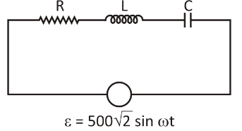
In a series RLC circuit, the r.m.s the voltage across the resistor and the inductor are respectively $400\,V$ and $700\,V$. If the equation for the applied voltage is $\varepsilon = 500\,\sqrt 2 \,\sin \omega t$, then the peak voltage across the capacitor is
A. $1200\,V$
B. $400\sqrt 2 \,V$
C. $400\,V$
D. $1200\sqrt 2 \,V$
Answer
600.3k+ views
Hint:Here we have to first find the value of the rms voltage across the capacitor then, rms square. After finding rms square we can find the value of peak voltage of the capacitor. The sum of AC power that causes the same heating effect as DC power is the RMS Voltage or Root Mean Square Voltage of an AC Waveform.
Complete step by step answer:
Given,
Applied voltage, $\varepsilon = 500\sqrt 2 \sin \omega t$
Voltage across the inductor,${E_L} = 700\,V$
Voltage across the resistor, ${E_R} = 400\,V$
$
{E_{rms}} = \dfrac{\varepsilon }{{\sqrt 2 }} \\
\Rightarrow {E_{rms}} = 500\,V \\ $
Now we find the rms value of the capacitor as:
$
{E_{rms}}^2 = {E_R}^2 + {\left( {{E_L} - {E_C}} \right)^2} \\
\Rightarrow 250000 = 160000 + {\left( {700 - {E_C}} \right)^2} \\
\Rightarrow {\left( {700 - {E_C}} \right)^2} = 90000 \\
\Rightarrow {E_c} = 400 \\ $
Thus, rms voltage applied across the capacitor is $400\,V$ .
Now, the peak voltage across the capacitor is given by:
$
\Rightarrow {E_ \circ } = \sqrt 2 \times {E_C} \\
\Rightarrow {E_ \circ } = \sqrt 2 \times 400 \\
\therefore {E_ \circ } = 400\sqrt 2 \,V \\ $
Hence, option B is correct.
Additional information:
Peak voltage: On any voltage waveform, Peak voltage is the maximum point or highest value of voltage. It is a power quality problem that arises when machines that use pulse width modulation are added to a power grid, such as a variable frequency drive.
RLC circuit: A RLC circuit (also known as a resonant circuit, tuning circuit, or LCR circuit) is an electrical circuit consisting of a series or parallel coupled resistor (R), inductor (L), and capacitor (C). A harmonic oscillator is created by this arrangement.
In terms of Phasors, the LCR circuit analysis can be best understood. A phasor is a quantity which rotates. If we take I as our reference axis for an inductor (L), then the voltage leads by ${90^ \circ }$ , and for the capacitor, the voltage lags by ${90^ \circ }$ . But there is still a phase in the resistance, current and voltage phasors. Reactance is the opposition of a circuit element to the flow of current due to the inductance or capacitance of that element in electrical and electronic systems.
Note:Here we have to find the rms voltage of the given applied voltage. If we directly use the applied voltage then our answer would be wrong. AC voltages and currents) are often given as RMS values in normal usage because this makes it easier to make a sensible connection with steady DC voltages and currents), such as from a battery.
Recently Updated Pages
Master Class 12 Economics: Engaging Questions & Answers for Success
Master Class 12 English: Engaging Questions & Answers for Success
Master Class 12 Social Science: Engaging Questions & Answers for Success
Master Class 12 Maths: Engaging Questions & Answers for Success
Master Class 12 Physics: Engaging Questions & Answers for Success
Master Class 9 General Knowledge: Engaging Questions & Answers for Success
Trending doubts
Which are the Top 10 Largest Countries of the World?
Draw a labelled sketch of the human eye class 12 physics CBSE
Differentiate between homogeneous and heterogeneous class 12 chemistry CBSE
Why is the cell called the structural and functional class 12 biology CBSE
Draw ray diagrams each showing i myopic eye and ii class 12 physics CBSE
Which is the correct genotypic ratio of mendel dihybrid class 12 biology CBSE