


For the circuit shown in the figure,
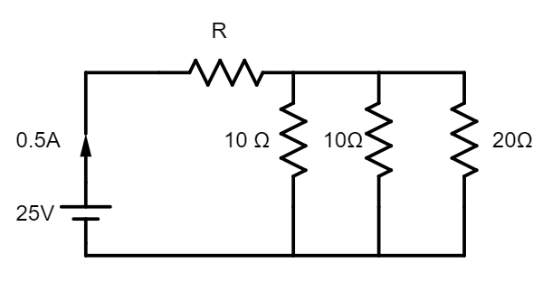
A) Resistance $R=46\Omega $
B) Current through $20\Omega $ resistance is $0.1A$
C) Potential difference across the middle resistance is $2V$
D) All of the above are true
Answer
591k+ views
Hint: The last three resistors in the figure are connected in parallel. The equivalent resistance of these resistors is calculated and is considered as a single resistor. This resistor is connected in series with the first resistor. From the formulas for series and parallel connections of resistors, we can calculate the unknown resistance. To calculate the current through the last resistor and the potential difference across the middle resistor, we proceed by following Kirchhoff’s rules.
Complete step by step answer:
Firstly, let us redraw the circuit by naming the components according to our comfortability.
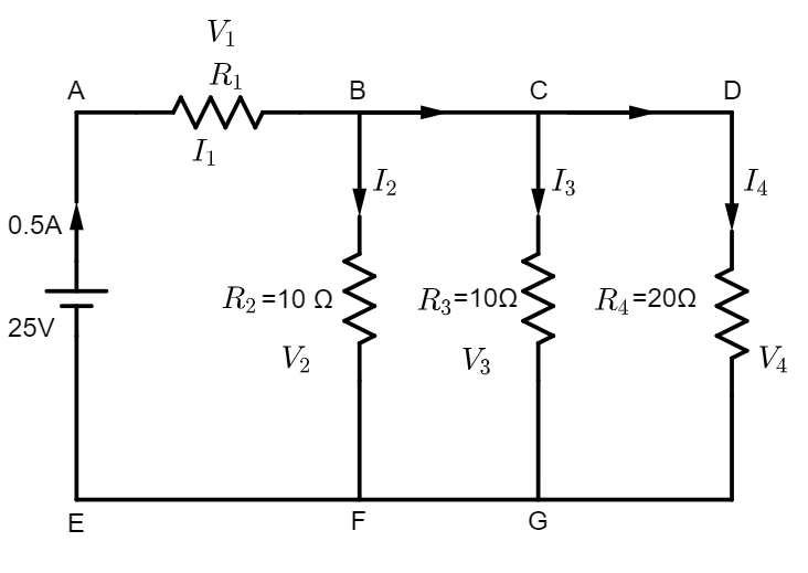
Let us name the resistors as
${{R}_{1}}$ = unknown, ${{R}_{2}}=10\Omega $, ${{R}_{3}}=10\Omega $ and ${{R}_{4}}=20\Omega $
Let the currents flowing through resistors ${{R}_{1}},{{R}_{2}},{{R}_{3}}$ and ${{R}_{4}}$ be ${{I}_{1}},{{I}_{2}},{{I}_{3}}$ and ${{I}_{4}}$, respectively.
Let the potential differences across the resistors ${{R}_{1}},{{R}_{2}},{{R}_{3}}$ and ${{R}_{4}}$ be ${{V}_{1}},{{V}_{2}},{{V}_{3}}$ and ${{V}_{4}}$, respectively.
It is given that $emf=25V$ and ${{I}_{1}}=0.5A$. We have to calculate the other parameters to see if the options given with the question are right.
From the figure, it is clear that ${{R}_{2}},{{R}_{3}}$ and ${{R}_{4}}$ are connected in parallel. Let the equivalent resistance of these resistances be ${{R}_{p}}$. Clearly, ${{R}_{p}}$ is given by
$\dfrac{1}{{{R}_{p}}}=\dfrac{1}{{{R}_{2}}}+\dfrac{1}{{{R}_{3}}}+\dfrac{1}{{{R}_{4}}}=\dfrac{1}{10}+\dfrac{1}{10}+\dfrac{1}{20}=\dfrac{5}{20}=\dfrac{1}{4}\Rightarrow {{R}_{p}}=4\Omega $
Now, ${{R}_{1}}$ and ${{R}_{p}}$ are connected in series. Let us consider the circuit to be a circuit with a single resistor ${{R}_{1}}+{{R}_{p}}$. To obtain the value of ${{R}_{1}}$, we can apply Ohm’s law as follows.
${{R}_{1}}+{{R}_{p}}=\dfrac{{{V}_{1}}}{{{I}_{1}}}=\dfrac{25}{0.5}=50\Omega \Rightarrow {{R}_{1}}+4\Omega =50\Omega \Rightarrow {{R}_{1}}=46\Omega $
Therefore, option A is correct.
Let us check the other options too.
To proceed, we have to apply Kirchhoff’s rules to find the current and potential difference through each resistor.
Kirchhoff’s current rule (KCL) says that the algebraic sum of the currents meeting at a junction in a closed electric circuit is zero. It says that
$\sum I=0$
Applying this rule in our circuit, we have ${{I}_{1}}={{I}_{2}}+({{I}_{1}}-{{I}_{2}})$ at node B and $({{I}_{1}}-{{I}_{2}})={{I}_{3}}+({{I}_{1}}-{{I}_{2}}-{{I}_{3}})$ at node C. Clearly, ${{I}_{4}}={{I}_{1}}-{{I}_{2}}-{{I}_{3}}$. Let this be equation 1.
Kirchhoff’s voltage rule (KVL) says that the algebraic sum of change in potential around any closed path of an electric circuit (or closed loop) involving resistors and cells in the loop is zero. It says that $\sum emf+\sum IR=0$
Applying this rule in closed loop ABFE, we have
$-25+{{I}_{1}}{{R}_{1}}+{{I}_{2}}{{R}_{2}}=0\Rightarrow -25+(0.5)(46)+{{I}_{2}}(10)=0\Rightarrow 10{{I}_{2}}=2\Rightarrow {{I}_{2}}=0.2A$
Again, applying KVL to the loop ABCGFE, we have
$-25+{{I}_{1}}{{R}_{1}}+{{I}_{3}}{{R}_{3}}=0\Rightarrow -25+(0.5)(10)+{{I}_{3}}(10)=0\Rightarrow 10{{I}_{3}}=2\Rightarrow {{I}_{3}}=\dfrac{2}{10}=0.2A$
Substituting the values of ${{I}_{2}}$ and ${{I}_{3}}$ in equation 1, we have
${{I}_{4}}={{I}_{1}}-{{I}_{2}}-{{I}_{3}}=0.5-0.2-0.2=0.1A$
Therefore, the current through the resistor $20\Omega $ is equal to $0.1A$. Hence, option B is also correct. Now, let us see if the third option is correct. It says that the potential difference across the middle resistor (${{R}_{1}}$ or ${{R}_{2}}$) is equal to $2V$.
Let us apply Ohm’s law to any of the middle resistors to obtain the value of potential difference across it.
$V=IR\Rightarrow {{V}_{2}}={{V}_{3}}=0.2A\times 10\Omega =2V$
The third option C is also correct. Therefore, option D is the correct option which says that all the statements mentioned in the options are correct.
Note:
Kirchhoff’s rules follow sign convention. To make it easy, in KCL, the current flowing towards a node is taken as positive and the current flowing away from the node is taken as negative. In KVL, while traversing a loop, if a negative pole of the cell is encountered first, then its emf is negative, otherwise positive.
Complete step by step answer:
Firstly, let us redraw the circuit by naming the components according to our comfortability.
Let us name the resistors as
${{R}_{1}}$ = unknown, ${{R}_{2}}=10\Omega $, ${{R}_{3}}=10\Omega $ and ${{R}_{4}}=20\Omega $
Let the currents flowing through resistors ${{R}_{1}},{{R}_{2}},{{R}_{3}}$ and ${{R}_{4}}$ be ${{I}_{1}},{{I}_{2}},{{I}_{3}}$ and ${{I}_{4}}$, respectively.
Let the potential differences across the resistors ${{R}_{1}},{{R}_{2}},{{R}_{3}}$ and ${{R}_{4}}$ be ${{V}_{1}},{{V}_{2}},{{V}_{3}}$ and ${{V}_{4}}$, respectively.
It is given that $emf=25V$ and ${{I}_{1}}=0.5A$. We have to calculate the other parameters to see if the options given with the question are right.
From the figure, it is clear that ${{R}_{2}},{{R}_{3}}$ and ${{R}_{4}}$ are connected in parallel. Let the equivalent resistance of these resistances be ${{R}_{p}}$. Clearly, ${{R}_{p}}$ is given by
$\dfrac{1}{{{R}_{p}}}=\dfrac{1}{{{R}_{2}}}+\dfrac{1}{{{R}_{3}}}+\dfrac{1}{{{R}_{4}}}=\dfrac{1}{10}+\dfrac{1}{10}+\dfrac{1}{20}=\dfrac{5}{20}=\dfrac{1}{4}\Rightarrow {{R}_{p}}=4\Omega $
Now, ${{R}_{1}}$ and ${{R}_{p}}$ are connected in series. Let us consider the circuit to be a circuit with a single resistor ${{R}_{1}}+{{R}_{p}}$. To obtain the value of ${{R}_{1}}$, we can apply Ohm’s law as follows.
${{R}_{1}}+{{R}_{p}}=\dfrac{{{V}_{1}}}{{{I}_{1}}}=\dfrac{25}{0.5}=50\Omega \Rightarrow {{R}_{1}}+4\Omega =50\Omega \Rightarrow {{R}_{1}}=46\Omega $
Therefore, option A is correct.
Let us check the other options too.
To proceed, we have to apply Kirchhoff’s rules to find the current and potential difference through each resistor.
Kirchhoff’s current rule (KCL) says that the algebraic sum of the currents meeting at a junction in a closed electric circuit is zero. It says that
$\sum I=0$
Applying this rule in our circuit, we have ${{I}_{1}}={{I}_{2}}+({{I}_{1}}-{{I}_{2}})$ at node B and $({{I}_{1}}-{{I}_{2}})={{I}_{3}}+({{I}_{1}}-{{I}_{2}}-{{I}_{3}})$ at node C. Clearly, ${{I}_{4}}={{I}_{1}}-{{I}_{2}}-{{I}_{3}}$. Let this be equation 1.
Kirchhoff’s voltage rule (KVL) says that the algebraic sum of change in potential around any closed path of an electric circuit (or closed loop) involving resistors and cells in the loop is zero. It says that $\sum emf+\sum IR=0$
Applying this rule in closed loop ABFE, we have
$-25+{{I}_{1}}{{R}_{1}}+{{I}_{2}}{{R}_{2}}=0\Rightarrow -25+(0.5)(46)+{{I}_{2}}(10)=0\Rightarrow 10{{I}_{2}}=2\Rightarrow {{I}_{2}}=0.2A$
Again, applying KVL to the loop ABCGFE, we have
$-25+{{I}_{1}}{{R}_{1}}+{{I}_{3}}{{R}_{3}}=0\Rightarrow -25+(0.5)(10)+{{I}_{3}}(10)=0\Rightarrow 10{{I}_{3}}=2\Rightarrow {{I}_{3}}=\dfrac{2}{10}=0.2A$
Substituting the values of ${{I}_{2}}$ and ${{I}_{3}}$ in equation 1, we have
${{I}_{4}}={{I}_{1}}-{{I}_{2}}-{{I}_{3}}=0.5-0.2-0.2=0.1A$
Therefore, the current through the resistor $20\Omega $ is equal to $0.1A$. Hence, option B is also correct. Now, let us see if the third option is correct. It says that the potential difference across the middle resistor (${{R}_{1}}$ or ${{R}_{2}}$) is equal to $2V$.
Let us apply Ohm’s law to any of the middle resistors to obtain the value of potential difference across it.
$V=IR\Rightarrow {{V}_{2}}={{V}_{3}}=0.2A\times 10\Omega =2V$
The third option C is also correct. Therefore, option D is the correct option which says that all the statements mentioned in the options are correct.
Note:
Kirchhoff’s rules follow sign convention. To make it easy, in KCL, the current flowing towards a node is taken as positive and the current flowing away from the node is taken as negative. In KVL, while traversing a loop, if a negative pole of the cell is encountered first, then its emf is negative, otherwise positive.
Recently Updated Pages
Master Class 12 Economics: Engaging Questions & Answers for Success
Master Class 12 Physics: Engaging Questions & Answers for Success
Master Class 12 English: Engaging Questions & Answers for Success
Master Class 12 Social Science: Engaging Questions & Answers for Success
Master Class 12 Maths: Engaging Questions & Answers for Success
Master Class 12 Business Studies: Engaging Questions & Answers for Success
Trending doubts
Which are the Top 10 Largest Countries of the World?
What are the major means of transport Explain each class 12 social science CBSE
Draw a labelled sketch of the human eye class 12 physics CBSE
Why cannot DNA pass through cell membranes class 12 biology CBSE
Differentiate between insitu conservation and exsitu class 12 biology CBSE
Draw a neat and well labeled diagram of TS of ovary class 12 biology CBSE