


Draw a labelled circuit diagram of a potentiometer to compare emfs of two cells. Write the working formula (Derivation not required).
Answer
633.3k+ views
Hint: A potentiometer consists of a galvanometer, a variable resistance, a battery. In the circuit for the comparison of the emfs of the two cells, the circuit will comprise two cells as well.
Complete step by step solution:
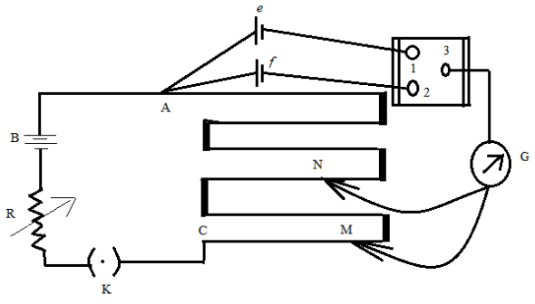
Figure: A potentiometer circuit designed for comparing emfs of two cells.
In the above figure, the wires run from point A to point C. The small vertical portions are metal strips connecting various sections of the wire. B is the battery, R is the variable resistance (the arrow indicates variable resistance) which is also known as the rheostat. e and f are the two cells whose emfs are to be compared. G is the galvanometer and N and M are the two points to which the galvanometer jockey is connected. The points marked 1,2 and 3 form a way key. K is the key of the circuit.
Working formula:
If ${{\varepsilon }_{1}}$ is the emf of cell e and ${{\varepsilon }_{2}}$is the emf of cell f, then the formula for comparison is given as,
$\dfrac{{{\varepsilon }_{1}}}{{{\varepsilon }_{2}}}=\dfrac{{{l}_{1}}}{{{l}_{2}}}$
where, ${{l}_{1}}$ and ${{l}_{2}}$ are the distances of point N and M respectively from point A.
Additional Information:
There is also an arrangement of potentiometers for determining the internal resistance of a cell, where we do not need to incorporate the two cells.
Note: Students must note that ${{l}_{1}}$ and ${{l}_{2}}$ are the distances from point A and not from the galvanometer G or point C. And to represent the variable resistance, it is always necessary to give the arrow across the resistance, else it does not represent a variable resistance.
Complete step by step solution:
Figure: A potentiometer circuit designed for comparing emfs of two cells.
In the above figure, the wires run from point A to point C. The small vertical portions are metal strips connecting various sections of the wire. B is the battery, R is the variable resistance (the arrow indicates variable resistance) which is also known as the rheostat. e and f are the two cells whose emfs are to be compared. G is the galvanometer and N and M are the two points to which the galvanometer jockey is connected. The points marked 1,2 and 3 form a way key. K is the key of the circuit.
Working formula:
If ${{\varepsilon }_{1}}$ is the emf of cell e and ${{\varepsilon }_{2}}$is the emf of cell f, then the formula for comparison is given as,
$\dfrac{{{\varepsilon }_{1}}}{{{\varepsilon }_{2}}}=\dfrac{{{l}_{1}}}{{{l}_{2}}}$
where, ${{l}_{1}}$ and ${{l}_{2}}$ are the distances of point N and M respectively from point A.
Additional Information:
There is also an arrangement of potentiometers for determining the internal resistance of a cell, where we do not need to incorporate the two cells.
Note: Students must note that ${{l}_{1}}$ and ${{l}_{2}}$ are the distances from point A and not from the galvanometer G or point C. And to represent the variable resistance, it is always necessary to give the arrow across the resistance, else it does not represent a variable resistance.
Recently Updated Pages
Master Class 12 Business Studies: Engaging Questions & Answers for Success
Master Class 12 Chemistry: Engaging Questions & Answers for Success
Master Class 12 Biology: Engaging Questions & Answers for Success
Class 12 Question and Answer - Your Ultimate Solutions Guide
Master Class 9 General Knowledge: Engaging Questions & Answers for Success
Master Class 9 Maths: Engaging Questions & Answers for Success
Trending doubts
Which are the Top 10 Largest Countries of the World?
Draw a labelled sketch of the human eye class 12 physics CBSE
Differentiate between homogeneous and heterogeneous class 12 chemistry CBSE
Sulphuric acid is known as the king of acids State class 12 chemistry CBSE
Why is the cell called the structural and functional class 12 biology CBSE
A dentist uses a small mirror that gives a magnification class 12 physics CBSE