


What is a transformer? Explain the principle, construction, working and theory of a transformer.
Answer
575.5k+ views
Hint – You can start by defining what a transformer is. Then move on to describe the principle behind the transformer. Then describe the basic setup of a transformer. Then finally write how a transformer works.
An electrical device that can change the A.C. current is known as a transformer.
Principle – A transformer works on the principle of mutual induction. Mutual induction is the phenomenon by which when the amount of magnetic flux linked with a coil changes, an E.M.F. is induced in the neighboring coil.
Construction –
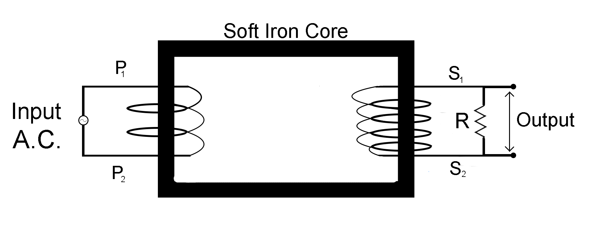
A transformer is made up of a rectangular iron core. Two coils, a primary $({P_{}})$ coil with two sides ${P_1}$ and ${P_2}$, and a secondary $(S)$ coil with two sides ${S_1}$ and ${S_2}$. Both these coils are insulated from the Ferro-magnetic iron core. The source of the alternate current is connected to the primary winding and the output is obtained through the secondary winding which is connected in parallel to a resistance $R$.
Working -
For an ideal transformer, we consider that resistances of the primary and secondary coils are negligible.
Let the $E.M.F.$ of the alternate current supplied by the A.C source be
${E_P} = {E_0}\sin \omega t$
Let’s assume that the primary winding to be a pure inductance, so here ${I_p}$will lag behind the voltage ${E_{P}}$ by $90^\circ $. Thus the power factor for primary coil becomes,$\cos \phi = \cos 90^\circ = 0$.
Let that the number of turns in primary wire be ${N_P}$ and secondary wire be ${N_S}$
According to faraday law, the induced $E.M.F.$ through one turn of both the coils will be the same.
Let the flux through one turn be $\phi $, the flux through the primary coil be ${\phi _p}$ and the flux through the secondary coil be ${\phi _S}$.
So ${\phi _p} = {N_P}\phi $
${\phi _S} = {N_S}\phi $
We also know by Faraday’s law
$E = \dfrac{{d\phi }}{{dt}}$
So for the primary coil this equation becomes
${E_S} = \dfrac{{d{\phi _S}}}{{dt}}$(Equation 1)
And for the secondary coil this equation becomes
${E_P} = \dfrac{{d{\phi _P}}}{{dt}}$(Equation 2)
Dividing equation 1 by equation 2
$\dfrac{{{E_S}}}{{{E_P}}} = \dfrac{{d{\phi _S}}}{{d{\phi _P}}} = \dfrac{{{N_S}\phi }}{{{N_P}\phi }}$
${E_S} = {E_p}\dfrac{{{N_S}}}{{{N_p}}}$(Equation 3)
We know that
$P = VI$
Here
$P = $Power
$V = $Voltage
$I = $Current
For primary coil this equation becomes
${P_P} = {E_P}{I_P}$(Equation 4)
For secondary coil this equation becomes
${P_S} = {E_S}{I_S}$(Equation 5)
For an ideal transformer no energy is lost, so
${P_p} = {P_S}$
${E_P}{I_P} = {E_S}{I_S}$
${I_S} = {I_p}\dfrac{{{E_p}}}{{{E_s}}}$$(\because \dfrac{{{E_p}}}{{{E_S}}} = \dfrac{{{N_p}}}{{{N_S}}})$
${I_S} = {I_p}\dfrac{{{N_p}}}{{{N_S}}}$
Note – A transformer that increases the A.C. voltage is known as a step up transformer (${N_S} > {N_p}$) and the transformer that decreases the A.C. voltage is known as a step down transformer (${N_S} < {N_p}$). Additionally an iron core is used because it is a ferromagnetic material which helps in increasing the strength of the magnetic field.
An electrical device that can change the A.C. current is known as a transformer.
Principle – A transformer works on the principle of mutual induction. Mutual induction is the phenomenon by which when the amount of magnetic flux linked with a coil changes, an E.M.F. is induced in the neighboring coil.
Construction –
A transformer is made up of a rectangular iron core. Two coils, a primary $({P_{}})$ coil with two sides ${P_1}$ and ${P_2}$, and a secondary $(S)$ coil with two sides ${S_1}$ and ${S_2}$. Both these coils are insulated from the Ferro-magnetic iron core. The source of the alternate current is connected to the primary winding and the output is obtained through the secondary winding which is connected in parallel to a resistance $R$.
Working -
For an ideal transformer, we consider that resistances of the primary and secondary coils are negligible.
Let the $E.M.F.$ of the alternate current supplied by the A.C source be
${E_P} = {E_0}\sin \omega t$
Let’s assume that the primary winding to be a pure inductance, so here ${I_p}$will lag behind the voltage ${E_{P}}$ by $90^\circ $. Thus the power factor for primary coil becomes,$\cos \phi = \cos 90^\circ = 0$.
Let that the number of turns in primary wire be ${N_P}$ and secondary wire be ${N_S}$
According to faraday law, the induced $E.M.F.$ through one turn of both the coils will be the same.
Let the flux through one turn be $\phi $, the flux through the primary coil be ${\phi _p}$ and the flux through the secondary coil be ${\phi _S}$.
So ${\phi _p} = {N_P}\phi $
${\phi _S} = {N_S}\phi $
We also know by Faraday’s law
$E = \dfrac{{d\phi }}{{dt}}$
So for the primary coil this equation becomes
${E_S} = \dfrac{{d{\phi _S}}}{{dt}}$(Equation 1)
And for the secondary coil this equation becomes
${E_P} = \dfrac{{d{\phi _P}}}{{dt}}$(Equation 2)
Dividing equation 1 by equation 2
$\dfrac{{{E_S}}}{{{E_P}}} = \dfrac{{d{\phi _S}}}{{d{\phi _P}}} = \dfrac{{{N_S}\phi }}{{{N_P}\phi }}$
${E_S} = {E_p}\dfrac{{{N_S}}}{{{N_p}}}$(Equation 3)
We know that
$P = VI$
Here
$P = $Power
$V = $Voltage
$I = $Current
For primary coil this equation becomes
${P_P} = {E_P}{I_P}$(Equation 4)
For secondary coil this equation becomes
${P_S} = {E_S}{I_S}$(Equation 5)
For an ideal transformer no energy is lost, so
${P_p} = {P_S}$
${E_P}{I_P} = {E_S}{I_S}$
${I_S} = {I_p}\dfrac{{{E_p}}}{{{E_s}}}$$(\because \dfrac{{{E_p}}}{{{E_S}}} = \dfrac{{{N_p}}}{{{N_S}}})$
${I_S} = {I_p}\dfrac{{{N_p}}}{{{N_S}}}$
Note – A transformer that increases the A.C. voltage is known as a step up transformer (${N_S} > {N_p}$) and the transformer that decreases the A.C. voltage is known as a step down transformer (${N_S} < {N_p}$). Additionally an iron core is used because it is a ferromagnetic material which helps in increasing the strength of the magnetic field.
Recently Updated Pages
Master Class 12 Economics: Engaging Questions & Answers for Success
Master Class 12 Biology: Engaging Questions & Answers for Success
Master Class 11 English: Engaging Questions & Answers for Success
Master Class 11 Physics: Engaging Questions & Answers for Success
Master Class 11 Computer Science: Engaging Questions & Answers for Success
Master Class 11 Chemistry: Engaging Questions & Answers for Success
Trending doubts
Which are the Top 10 Largest Countries of the World?
Draw a labelled sketch of the human eye class 12 physics CBSE
Why is the cell called the structural and functional class 12 biology CBSE
Draw ray diagrams each showing i myopic eye and ii class 12 physics CBSE
Differentiate between homogeneous and heterogeneous class 12 chemistry CBSE
Which is the correct genotypic ratio of mendel dihybrid class 12 biology CBSE