


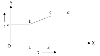
A flexible wire bent in the form of a circle is placed in a uniform magnetic field perpendicularly to the plane of coil. The radius of the coil changes as shown in figure. The graph of magnitude of induced emf in the coil is represented by
A.
B.
C.
D.
Answer
566.4k+ views
Hint:Use the formulae for flux, induced emf and area of the circle. Using these equations, derive the formula for induced emf in the circular wire and check on which physical quantity the induced emf depends. Check the variation of radius with time from the given graph and determine the graph for induced emf versus time.
Formulae used:
The flux \[\phi \] linked with a surface is
\[\phi = BA\] …… (1)
Here, \[B\] is the magnetic field and \[A\] is the area of the surface.
The emf induced is given by
\[e = - \dfrac{{d\phi }}{{dt}}\] …… (2)
Here, \[\phi \] is the flux and \[t\] is the time.
The area \[A\] of a circle is
\[A = \pi {r^2}\] …… (3)
Here, \[r\] is the radius of the circle.
Complete step by step answer:
We have given that a flexible wire is bent into a circle of non-uniform radius \[r\]. Let us determine the formula for induced emf \[e\] in the circular wire.
Substitute \[BA\] for \[\phi \] in equation (2).
\[e = - \dfrac{{d\left( {BA} \right)}}{{dt}}\]
Substitute \[\pi {r^2}\] for \[A\] in the above equation.
\[e = - \dfrac{{d\left( {B\pi {r^2}} \right)}}{{dt}}\]
\[ \Rightarrow e = - \pi B\dfrac{{d\left( {{r^2}} \right)}}{{dt}}\]
\[ \Rightarrow e = - 2\pi rB\dfrac{{dr}}{{dt}}\]
\[ \Rightarrow \left| e \right| = 2\pi rB\dfrac{{dr}}{{dt}}\]
From the above equation, we can see that the magnitude of induced emf in the circular wire depends on the rate of change of radius of the wire with time.From the given graph of radius versus time, we can see that the radius of the circular wire from point a to b and c to d is constant. Hence, the rate of change of radius for these two sections is zero. Hence, the value of induced emf for a to b and c to d is zero.
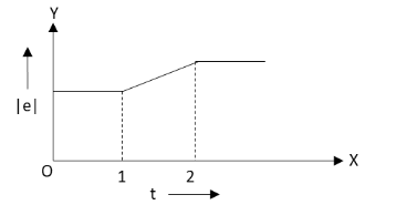
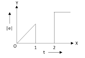
There is induced emf in the circular wire only for the section b to c shown in the given graph.There is a linear increase in the radius from b to c with time. Hence, the induced emf from b to c will also increase linearly.This type of increase in induced emf is shown only in the graph given in the option B.
Hence, the correct option is B.
Note: The students should be careful while deriving the formula for the induced emf in the circular wire. Also, the students should remember that we have asked to identify the graph for magnitude of induced emf versus time for the given wire and not the induced emf versus time (as this graph will give a decreasing value of emf with time due to negative sign in the formula).
Formulae used:
The flux \[\phi \] linked with a surface is
\[\phi = BA\] …… (1)
Here, \[B\] is the magnetic field and \[A\] is the area of the surface.
The emf induced is given by
\[e = - \dfrac{{d\phi }}{{dt}}\] …… (2)
Here, \[\phi \] is the flux and \[t\] is the time.
The area \[A\] of a circle is
\[A = \pi {r^2}\] …… (3)
Here, \[r\] is the radius of the circle.
Complete step by step answer:
We have given that a flexible wire is bent into a circle of non-uniform radius \[r\]. Let us determine the formula for induced emf \[e\] in the circular wire.
Substitute \[BA\] for \[\phi \] in equation (2).
\[e = - \dfrac{{d\left( {BA} \right)}}{{dt}}\]
Substitute \[\pi {r^2}\] for \[A\] in the above equation.
\[e = - \dfrac{{d\left( {B\pi {r^2}} \right)}}{{dt}}\]
\[ \Rightarrow e = - \pi B\dfrac{{d\left( {{r^2}} \right)}}{{dt}}\]
\[ \Rightarrow e = - 2\pi rB\dfrac{{dr}}{{dt}}\]
\[ \Rightarrow \left| e \right| = 2\pi rB\dfrac{{dr}}{{dt}}\]
From the above equation, we can see that the magnitude of induced emf in the circular wire depends on the rate of change of radius of the wire with time.From the given graph of radius versus time, we can see that the radius of the circular wire from point a to b and c to d is constant. Hence, the rate of change of radius for these two sections is zero. Hence, the value of induced emf for a to b and c to d is zero.
There is induced emf in the circular wire only for the section b to c shown in the given graph.There is a linear increase in the radius from b to c with time. Hence, the induced emf from b to c will also increase linearly.This type of increase in induced emf is shown only in the graph given in the option B.
Hence, the correct option is B.
Note: The students should be careful while deriving the formula for the induced emf in the circular wire. Also, the students should remember that we have asked to identify the graph for magnitude of induced emf versus time for the given wire and not the induced emf versus time (as this graph will give a decreasing value of emf with time due to negative sign in the formula).
Recently Updated Pages
Master Class 12 Economics: Engaging Questions & Answers for Success
Master Class 12 Physics: Engaging Questions & Answers for Success
Master Class 12 English: Engaging Questions & Answers for Success
Master Class 12 Social Science: Engaging Questions & Answers for Success
Master Class 12 Maths: Engaging Questions & Answers for Success
Master Class 12 Business Studies: Engaging Questions & Answers for Success
Trending doubts
Why cannot DNA pass through cell membranes class 12 biology CBSE
Draw a neat and well labeled diagram of TS of ovary class 12 biology CBSE
In a human foetus the limbs and digits develop after class 12 biology CBSE
AABbCc genotype forms how many types of gametes a 4 class 12 biology CBSE
Differentiate between homogeneous and heterogeneous class 12 chemistry CBSE
The correct structure of ethylenediaminetetraacetic class 12 chemistry CBSE