


An Overview of PWM
Pulse Width Modulation or PWM method is one of the most frequently used methods to control semiconductor devices. In the PWM technique, analog signals are created with the use of several types of digital devices. The created signals carry the impulse in the square wave form. Thus, it is dependent on time, which means it can be high or low at any given time. PWM reduced the power range gained by the electrical signal. It can be executed by turning the PWM signals into various parts. This technique is mostly used in communication systems.
What is Pulse Width Modulation?
The answer to the question what is pwm technique or pulse width modulatin technique is that it is a type of modulation technique used to modulate the signals. It is used to lower the average power conveyed by an electrical sign by changing over the signal into discrete parts. In the PWM technique, the sign's energy is circulated through a progression of pulses as opposed to a consistently fluctuating (analog) signal.
How is a Pulse Width Modulation Signal Generated?
A pwm signal can be generated by a monostable multivibrator. Monostable multivibrator has only one stable state and give single output pulse when external trigger is given. A monostable multivibrator circuit can be constructed using an operational amplifier comparator. The modulating signal structures one piece of the input to the comparator, while the non-sinusoidal waveforms the other piece of the information. The comparator looks at two signals and produces a PWM signal as its result waveform. In the event that the sawtooth signal or non sinusoidal signal is more than the modulating signal, the output is in a "High" state. The worth of the size decides the comparator yield which characterizes the width of the pulse created at the output.
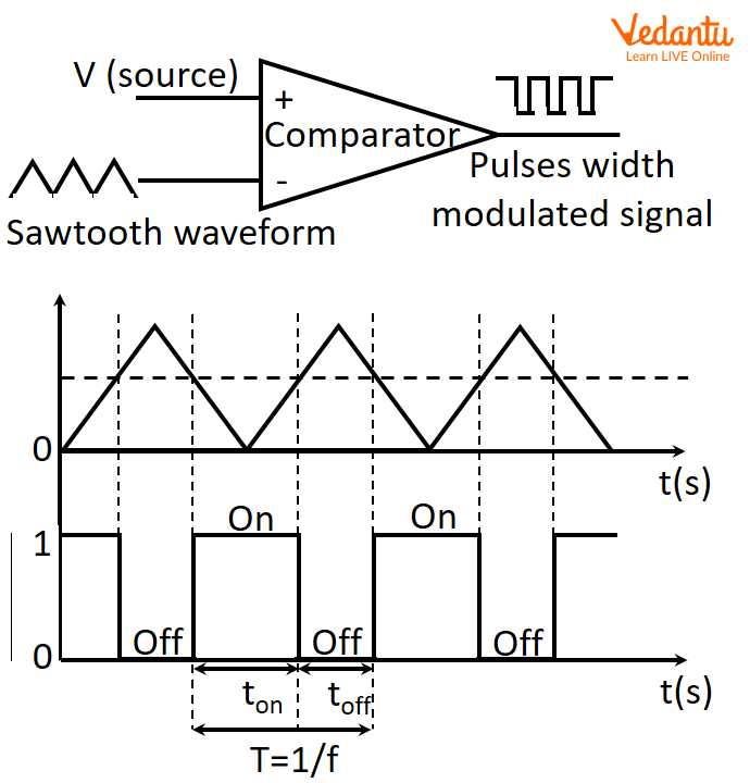
PMW Signal
Comparator generating pulse width modulation.
Duty Cycle of PWM
At the point when the signal is high, we refer to this as "on time". To portray how much "on time", we utilize the idea of duty cycle. Duty cycle is estimated in percentage. The percentage of duty cycle explicitly depicts the percentage of time a digital signal is on over an interval or timeframe. This period is the opposite of the frequency of the waveform.
On the off chance that a digital signal invests half of the time in and the other half off, we would agree that the digital signal has a duty cycle of 50% and looks like an optimal square wave. On the off chance that the percentage is higher than 50%, the digital signal invests more time in the high state than the low state as well as the other way around on the off chance that the duty cycle is under 50%. Here is a diagram that shows these three situations:
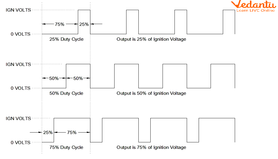
Duty Cycle
Ignition voltage variation with duty cycle.
Frequency of PWM
A frequency or period is well defined for controlling a specific servo. Regularly, a servo engine expects an update each 20 ms with a pulse between 1 ms and 2 ms. This compares to an obligation pattern of 5% to 10% at 50 Hz. Presently, assuming the pulse is at 1.5 ms, the servo engine will be at 90-degrees, at 1 ms, 0-degrees, and at 2 ms, 180 degrees. In outline, by refreshing the servo with a value between 1 ms and 2ms, we can get a full scope of motion.
PWM is additionally at present in an unambiguous communication system, and its duty cycle is being used to pass data on over communication channels. So, PWM is a technique to create low-frequency output signals from high-frequency pulses.
$\text{Frequency} =\frac{1}{\text{Time period}}$
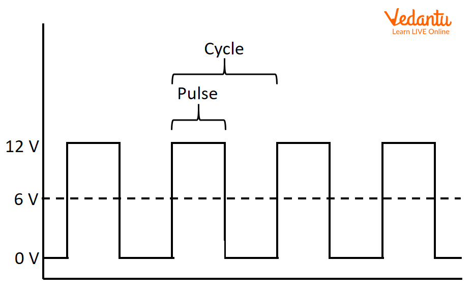
Frequency of PWM
Applications of PWM
PWM is used in many applications as given below.
In electronic gadgets, modulation is the utilization of a controlling or changing impact on something. We likewise refer to it as a variety in the pitch, strength, or tone of a frequency, as in the human voice.
We regularly experience modulation procedures being used for the control of gadgets like DC motors or LEDs.
PWM matched with maximum power point tracking (MPPT) is one of the important strategies for lowering a solar panel's output to work with its utilization by a battery.
You have some control over the brightness of a LED by changing the duty cycle. With a RGB (red green blue) LED, you have some control over the amount of every one of the three colors you need in the blend of variety by diminishing them with different sums.
The PWM procedure controls the fan inside a CPU of the PC, subsequently effectively disseminating the heat.
Summary
In this article, we learnt about the pulse width modulation (PWM) method which is used to modulate the signals. The utilization of pulse width modulation in different applications including complex control circuits has been discussed. We learnt that monostable multivibrator circuit constructed using comparator can be used to generate pwm signals along with the glimpse of applications and examples.
FAQs on PWM (Pulse Width Modulation)
1. What is Pulse Width Modulation (PWM) and what is its basic principle?
Pulse Width Modulation (PWM) is a technique used to control the power delivered to electrical devices by using a digital signal. Its fundamental principle is to vary the duration of the 'on-time' (the pulse width) of a square wave signal while keeping the frequency constant. By changing this duty cycle (the ratio of on-time to the total period), you can control the average voltage and thus the power supplied to a load, effectively creating an analog-like result from a digital source.
2. How are the duty cycle and frequency defined in a PWM signal?
In a PWM signal, the key parameters are:
- Duty Cycle: This is the percentage of time the signal remains in the 'HIGH' or 'on' state during one complete cycle. A 25% duty cycle means the signal is high for 25% of the time and low for 75%.
- Frequency: This is the number of cycles a PWM signal completes per second, measured in Hertz (Hz). The frequency determines how quickly the signal switches between HIGH and LOW states. For many applications, like motor control, the frequency is set high enough so that the switching is not noticeable.
3. How does changing the duty cycle of a PWM signal control the brightness of an LED?
Changing a PWM signal's duty cycle controls an LED's brightness by adjusting the average power it receives. Because the PWM signal switches on and off very rapidly, the human eye cannot perceive the flicker. Instead, it averages the light output. A low duty cycle (e.g., 10%) means the LED is on for only a short portion of each cycle, resulting in low average power and dim light. A high duty cycle (e.g., 90%) keeps the LED on for most of the cycle, delivering high average power and making it appear bright.
4. What are the basic components required to generate a PWM signal?
A basic PWM signal can be generated using a simple circuit involving three main components:
- A comparator (often an operational amplifier).
- A modulating signal, which is the desired analog voltage level you want to represent.
- A reference waveform, typically a sawtooth or triangle wave with a fixed frequency.
The comparator compares the modulating signal with the reference waveform. It outputs a HIGH signal when the modulating signal's voltage is higher than the reference waveform's voltage and a LOW signal otherwise, creating the PWM output.
5. What is the difference between controlling power with PWM versus using a variable resistor?
The key difference is efficiency. When using a variable resistor (rheostat) to control power to a load like a motor, the resistor dissipates the unused energy as heat, which is highly inefficient. In contrast, PWM controls power by rapidly switching the controlling element (like a transistor) completely ON or completely OFF. In these states, the transistor has very low resistance (ON) or almost zero current (OFF), resulting in minimal power loss and much higher efficiency.
6. How do you calculate the average output voltage from a PWM signal?
You can calculate the average voltage of a PWM signal with a simple formula that relates the duty cycle to the high voltage level of the signal. The formula is:
Average Voltage = Duty Cycle (%) × Vhigh
For example, if you have a PWM signal that switches between 0V (Vlow) and 5V (Vhigh) and it has a duty cycle of 60%, the average voltage would be 0.60 × 5V = 3V.
7. What are some common real-world examples and applications of PWM?
Pulse Width Modulation is used in a wide variety of applications due to its efficiency and precise control. Common examples include:
- Motor Control: Controlling the speed of DC motors in robotics, fans, and pumps.
- LED Lighting: Dimming LEDs and creating different colours in RGB LEDs.
- Audio Amplifiers: Class-D amplifiers use PWM to create a high-power output with high efficiency.
- Power Supplies: Switch-mode power supplies use PWM to regulate output voltage efficiently.
- Servo Motors: In remote control systems, the width of the pulse (typically between 1ms and 2ms) directly corresponds to the angle of the servo motor's shaft.