


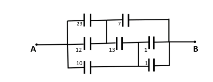
The equivalent capacitance across A and B is: (all capacitances are in $\mu F$ )
$\begin{align}
& (A)\dfrac{28}{3}\mu F \\
& (B)\dfrac{15}{2}\mu F \\
& (C)15\mu F \\
& (D)\text{None of these} \\
\end{align}$
Answer
559.2k+ views
Hint: We will first break down the above circuits into much smaller and easier to understand equivalent capacitance systems. Once, we do that we will use the formula for net capacitance in series and parallel to solve each branch step by step. And, then we can finally get the required capacitance between the two points A and B.
Complete step-by-step answer:
We will first solve the branches that are easy to solve and then simplify our circuit.
In the first step we will work on the dashed section shown in the figure below:
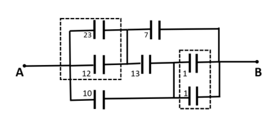
The $23\mu F$ and $12\mu F$capacitors are connected in parallel so their resultant could be written as $35\mu F$ . Also, when going through point B the two $1\mu F$ capacitors are connected in parallel, so their resultant will be $2\mu F$ .
Thus, our new circuit will be reconstructed as follows:
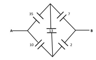
Now, this circuit looks like a wheatstone bridge. So, we will check for the condition of a balanced wheatstone bridge.
In the left-hand side of the divider capacitance, we have:
$\begin{align}
& \Rightarrow L.H.S.=\dfrac{35}{10} \\
& \therefore L.H.S.=3.5 \\
\end{align}$
And in the right-hand side of the divider capacitance, we have:
$\begin{align}
& \Rightarrow R.H.S.=\dfrac{7}{2} \\
& \therefore R.H.S.=3.5 \\
\end{align}$
This implies that the ratio of capacitance is equal at both the sides of the divider. Thus, it is a perfectly balanced wheatstone bridge. So the divider capacitor will act as an open circuit. Thus our new circuit becomes:
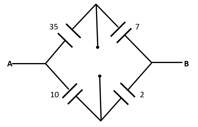
The above circuit is a simple circuit having series and parallel capacitors.
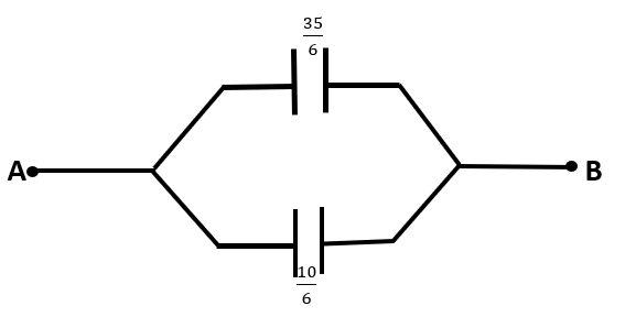
In the top branch of the circuit, equivalent capacitance (say${{C}_{1}}$ ) is equal to:
$\begin{align}
& \Rightarrow {{C}_{1}}=\dfrac{35\times 7}{35+7}\mu F \\
& \therefore {{C}_{1}}=\dfrac{35}{6}\mu F \\
\end{align}$
And, in the bottom branch of the circuit, equivalent capacitance (say${{C}_{2}}$) is equal to:
$\begin{align}
& \Rightarrow {{C}_{2}}=\dfrac{10\times 2}{10+2}\mu F \\
& \therefore {{C}_{2}}=\dfrac{10}{6}\mu F \\
\end{align}$
Now, the net capacitance between A and B could be given by the summation of ${{C}_{1}}$and ${{C}_{2}}$as they are connected in parallel. This circuit is represented below:
Thus, the equivalent capacitance between A and B is:
$\begin{align}
& \Rightarrow {{C}_{AB}}=\dfrac{35}{6}+\dfrac{10}{6} \\
& \Rightarrow {{C}_{AB}}=\dfrac{45}{6}\mu F \\
& \therefore {{C}_{AB}}=\dfrac{15}{2}\mu F \\
\end{align}$
Hence, the equivalent capacitance across A and B is $\dfrac{15}{2}\mu F$.
So, the correct answer is “Option B”.
Note: In complex circuit problems like these, we should break the circuit into a smaller and easier to understand circuit at every step of the process. Also, we should keep looking for special conditions like Wheatstone bridge, as they make our problems significantly easier to solve and less complex.
Complete step-by-step answer:
We will first solve the branches that are easy to solve and then simplify our circuit.
In the first step we will work on the dashed section shown in the figure below:
The $23\mu F$ and $12\mu F$capacitors are connected in parallel so their resultant could be written as $35\mu F$ . Also, when going through point B the two $1\mu F$ capacitors are connected in parallel, so their resultant will be $2\mu F$ .
Thus, our new circuit will be reconstructed as follows:
Now, this circuit looks like a wheatstone bridge. So, we will check for the condition of a balanced wheatstone bridge.
In the left-hand side of the divider capacitance, we have:
$\begin{align}
& \Rightarrow L.H.S.=\dfrac{35}{10} \\
& \therefore L.H.S.=3.5 \\
\end{align}$
And in the right-hand side of the divider capacitance, we have:
$\begin{align}
& \Rightarrow R.H.S.=\dfrac{7}{2} \\
& \therefore R.H.S.=3.5 \\
\end{align}$
This implies that the ratio of capacitance is equal at both the sides of the divider. Thus, it is a perfectly balanced wheatstone bridge. So the divider capacitor will act as an open circuit. Thus our new circuit becomes:
The above circuit is a simple circuit having series and parallel capacitors.
In the top branch of the circuit, equivalent capacitance (say${{C}_{1}}$ ) is equal to:
$\begin{align}
& \Rightarrow {{C}_{1}}=\dfrac{35\times 7}{35+7}\mu F \\
& \therefore {{C}_{1}}=\dfrac{35}{6}\mu F \\
\end{align}$
And, in the bottom branch of the circuit, equivalent capacitance (say${{C}_{2}}$) is equal to:
$\begin{align}
& \Rightarrow {{C}_{2}}=\dfrac{10\times 2}{10+2}\mu F \\
& \therefore {{C}_{2}}=\dfrac{10}{6}\mu F \\
\end{align}$
Now, the net capacitance between A and B could be given by the summation of ${{C}_{1}}$and ${{C}_{2}}$as they are connected in parallel. This circuit is represented below:
Thus, the equivalent capacitance between A and B is:
$\begin{align}
& \Rightarrow {{C}_{AB}}=\dfrac{35}{6}+\dfrac{10}{6} \\
& \Rightarrow {{C}_{AB}}=\dfrac{45}{6}\mu F \\
& \therefore {{C}_{AB}}=\dfrac{15}{2}\mu F \\
\end{align}$
Hence, the equivalent capacitance across A and B is $\dfrac{15}{2}\mu F$.
So, the correct answer is “Option B”.
Note: In complex circuit problems like these, we should break the circuit into a smaller and easier to understand circuit at every step of the process. Also, we should keep looking for special conditions like Wheatstone bridge, as they make our problems significantly easier to solve and less complex.
Recently Updated Pages
Master Class 12 Business Studies: Engaging Questions & Answers for Success
Master Class 12 Biology: Engaging Questions & Answers for Success
Master Class 12 Chemistry: Engaging Questions & Answers for Success
Class 12 Question and Answer - Your Ultimate Solutions Guide
Master Class 11 Social Science: Engaging Questions & Answers for Success
Master Class 11 English: Engaging Questions & Answers for Success
Trending doubts
Which are the Top 10 Largest Countries of the World?
Draw a labelled sketch of the human eye class 12 physics CBSE
Differentiate between homogeneous and heterogeneous class 12 chemistry CBSE
Sulphuric acid is known as the king of acids State class 12 chemistry CBSE
Why is the cell called the structural and functional class 12 biology CBSE
Which is the correct genotypic ratio of mendel dihybrid class 12 biology CBSE