


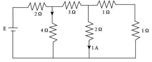
The e.m.f. of the cell shown in the figure is
(A) $12\;{\rm{V}}$
(B) $13\;{\rm{V}}$
(C) $16\;{\rm{V}}$
(D) $18\;{\rm{V}}$
Answer
574.2k+ views
Hint:First, we will draw the circuit diagram with current distribution in various resistance and resolve some resistance to get some idea about current flow. After this, we can apply KVL in the various loops of the circuit to determine the emf of the cell.
Complete step by step answer:
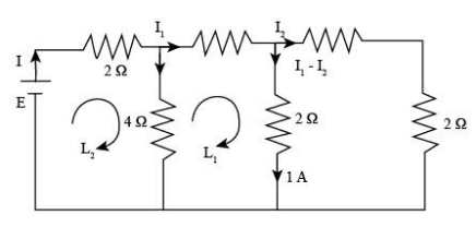
Draw the circuit diagram with the current distribution.
In the diagram, we resolve the two right-side resistance, which is in series. Here, we will calculate the voltage across A and B, so
$
{V_A} - {V_B} = 2\;\Omega \times 1\;{\rm{A}}\\
\Rightarrow{V_A} - {V_B} = 2\;{\rm{V}}
$
Now we know that the ${V_A} - {V_B} = 2\;{\rm{V}}$, so calculate current ${I_2}$ with the help of ${V_A} - {V_B}$.
Therefore, we get
$
2\;{\rm{V}} = {I_2} \times 2\;\Omega \\
\Rightarrow{I_2} = \dfrac{{2\;{\rm{V}}}}{{2\;\Omega }}\\
\Rightarrow{I_2} = 1\;{\rm{A}}$
From the diagram we will use ${I_1} - {I_2} = \;{\rm{1A}}$ for the determination of ${I_1}$ current, so substitute the value of \[{I_2}\] equation.
\[
{I_1} - 1\;{\rm{A}} = 1\;{\rm{A}}\\
\Rightarrow {I_1} = 2\;{\rm{A}}
\]
Now, we will apply the KVL in loop ${L_1}$ to determine the current $I$.
Therefore, we get
$\left( { - 2\;\Omega {I_1}} \right) - \left( {2\;\Omega
\times 1\;{\rm{A}}} \right) + 6\;\Omega \left( {I - {I_1}} \right) = 0$
Here, we use a negative sign where the current direction is clockwise and a positive sign where the current direction is anticlockwise in the circuit.
Substitute ${I_1} = 2\;{\rm{A}}$ in the above equation.
\[
\left( { - 2\;\;\Omega \times 2\;{\rm{A}}} \right) - \left( {2\;\Omega \times 1\;{\rm{A}}} \Rightarrow\right) + 6\;\Omega \left( {I - 2\;{\rm{A}}} \right) = 0\\
\Rightarrow \left( { - 4\;{\rm{V}}} \right) - \left( {2\;{\rm{V}}} \right) + 6\;\Omega I - 12\;{\rm{V}} = 0\\
\Rightarrow I = \dfrac{{18\;{\rm{V}}}}{{6\;\Omega }}\\
\Rightarrow I = 3\;{\rm{A}}
\]
Again we will apply KVL in the loop ${L_2}$ to determine the emf of the cell.
Therefore, we get
$E - 2\;\Omega I - 6\;\Omega \left( {I - {I_1}} \right) = 0$
Here, $E$ is the e.m.f of the cell.
Substitute the values in the above equation.
\[
E - 2\;\Omega \left( {{\rm{3}}\;{\rm{A}}} \right) - 6\;\Omega \left( {{\rm{3}}\,{\rm{A - 2}}\;{\rm{A}}} \right) = 0\\
\Rightarrow E - 6\;{\rm{V}} - 6\;{\rm{V}} = 0\\
\therefore E = 12\;V\]
Therefore, e.m.f. of the cell is $12\;{\rm{V}}$ and option (A) is correct.
Note:In this question, the application of KVL is an important part of the solution. So, use the correct sign convention while applying the KVL in the two loops of the circuits. If we use the wrong sign convention, then our calculation will become wrong, and we will get the incorrect value of the e.m.f of the cell.
Complete step by step answer:
Draw the circuit diagram with the current distribution.
In the diagram, we resolve the two right-side resistance, which is in series. Here, we will calculate the voltage across A and B, so
$
{V_A} - {V_B} = 2\;\Omega \times 1\;{\rm{A}}\\
\Rightarrow{V_A} - {V_B} = 2\;{\rm{V}}
$
Now we know that the ${V_A} - {V_B} = 2\;{\rm{V}}$, so calculate current ${I_2}$ with the help of ${V_A} - {V_B}$.
Therefore, we get
$
2\;{\rm{V}} = {I_2} \times 2\;\Omega \\
\Rightarrow{I_2} = \dfrac{{2\;{\rm{V}}}}{{2\;\Omega }}\\
\Rightarrow{I_2} = 1\;{\rm{A}}$
From the diagram we will use ${I_1} - {I_2} = \;{\rm{1A}}$ for the determination of ${I_1}$ current, so substitute the value of \[{I_2}\] equation.
\[
{I_1} - 1\;{\rm{A}} = 1\;{\rm{A}}\\
\Rightarrow {I_1} = 2\;{\rm{A}}
\]
Now, we will apply the KVL in loop ${L_1}$ to determine the current $I$.
Therefore, we get
$\left( { - 2\;\Omega {I_1}} \right) - \left( {2\;\Omega
\times 1\;{\rm{A}}} \right) + 6\;\Omega \left( {I - {I_1}} \right) = 0$
Here, we use a negative sign where the current direction is clockwise and a positive sign where the current direction is anticlockwise in the circuit.
Substitute ${I_1} = 2\;{\rm{A}}$ in the above equation.
\[
\left( { - 2\;\;\Omega \times 2\;{\rm{A}}} \right) - \left( {2\;\Omega \times 1\;{\rm{A}}} \Rightarrow\right) + 6\;\Omega \left( {I - 2\;{\rm{A}}} \right) = 0\\
\Rightarrow \left( { - 4\;{\rm{V}}} \right) - \left( {2\;{\rm{V}}} \right) + 6\;\Omega I - 12\;{\rm{V}} = 0\\
\Rightarrow I = \dfrac{{18\;{\rm{V}}}}{{6\;\Omega }}\\
\Rightarrow I = 3\;{\rm{A}}
\]
Again we will apply KVL in the loop ${L_2}$ to determine the emf of the cell.
Therefore, we get
$E - 2\;\Omega I - 6\;\Omega \left( {I - {I_1}} \right) = 0$
Here, $E$ is the e.m.f of the cell.
Substitute the values in the above equation.
\[
E - 2\;\Omega \left( {{\rm{3}}\;{\rm{A}}} \right) - 6\;\Omega \left( {{\rm{3}}\,{\rm{A - 2}}\;{\rm{A}}} \right) = 0\\
\Rightarrow E - 6\;{\rm{V}} - 6\;{\rm{V}} = 0\\
\therefore E = 12\;V\]
Therefore, e.m.f. of the cell is $12\;{\rm{V}}$ and option (A) is correct.
Note:In this question, the application of KVL is an important part of the solution. So, use the correct sign convention while applying the KVL in the two loops of the circuits. If we use the wrong sign convention, then our calculation will become wrong, and we will get the incorrect value of the e.m.f of the cell.
Recently Updated Pages
Master Class 12 Economics: Engaging Questions & Answers for Success
Master Class 12 Physics: Engaging Questions & Answers for Success
Master Class 12 English: Engaging Questions & Answers for Success
Master Class 12 Social Science: Engaging Questions & Answers for Success
Master Class 12 Maths: Engaging Questions & Answers for Success
Master Class 12 Business Studies: Engaging Questions & Answers for Success
Trending doubts
Which are the Top 10 Largest Countries of the World?
What are the major means of transport Explain each class 12 social science CBSE
Draw a labelled sketch of the human eye class 12 physics CBSE
What is a transformer Explain the principle construction class 12 physics CBSE
Why cannot DNA pass through cell membranes class 12 biology CBSE
Differentiate between insitu conservation and exsitu class 12 biology CBSE