


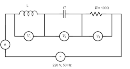
In the given circuit, the readings of voltmeters $V_1$ and $V_2$ are $300\;V$ each. The reading of the voltmeter $V_3$ and ammeter$\;A$ are respectively:
A). $100\;V$, $2.0\;A$
B). $150\;V$, $2.2\;A$
C). $220\;V$, $2.2\;A$
D). $220\;V$, $2.0\;A$
Answer
542.7k+ views
Hint: Sketch out a phasor diagram for the alternating voltages across each of the circuit elements of the given series LCR circuit. Then determine the potential difference across the resistor from the phasor diagram, provided that the voltage across the inductor and capacitor are out-of-phase with respect to each other. To this end, determine the reading on the ammeter given that the current through it will be due to the current through the resistor.
Formula Used:
Ohm’s Law: $I = \dfrac{V}{R}$
Complete step-by-step solution:
We know that the circuit given to us is a series LCR-circuit, which is a resonant circuit consisting of an inductor (L), a capacitor (C) and a resistor (R). Each element is connected in parallel with a voltmeter that measures the voltage drop across it. The working of this circuit can be better understood by employing the use of phasors.
Phasors are a graphical representation of the magnitude and directional relationship between two or more alternating quantities and are usually modelled in the cartesian plane. The potential across the inductor and capacitor and the current flowing through all elements are alternating with time and are usually represented as sinusoidal functions of angular frequency of oscillations and time. We can thus use phasors for the analysis of the LCR circuit.
The series LCR circuit given to us has a single loop (besides the voltmeters) with the same instantaneous current flowing through the loop for each circuit element. However, this means that the individual voltage drops across each circuit element will be out-of-phase with each other, i.e., if instantaneous current is defined as:
$I(t) = I_{max}\;sin(\omega t)$
Then the instantaneous voltage across the resistor $V_{R}$ will be in-phase with current,
The instantaneous voltage across the inductor $V_{L}$ will lead the current by $\dfrac{\pi}{2}$ or $90^{\circ}$, and
The instantaneous voltage across the capacitor $V_{C}$ will lag behind the current by $\dfrac{\pi}{2}$ or $90^{\circ}$.
Therefore, $V_L$ and $V_C$ are $\pi$ or $180^{\circ}$ out of phase and in opposition to each other, as shown in the phasor diagram below.
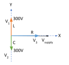
We have $|\vec{V_L}|= V_1 = 300\;V$, $|\vec{V_C}| = V_2 = 300\;V$, $|\vec{V_R}|=V_3$ and $V_{supply} = 200\;V$
From the diagram we see that $\vec{V_L}$ and $\vec{V_{C}}$ are opposite to each other and since they have the same magnitude, they get vectorially cancelled out.
Now, the resultant of $\vec{V_R}$, $\vec{V_L}$ and $\vec{V_C}$ is nothing but the supply voltage, i.e.,
$V_{supply} = \sqrt{|\vec{V_R}^2| + \left(|\vec{V_L}|-|\vec{V_C}|\right)^2}$
$\Rightarrow 200 = \sqrt{V_3^2 + \left(300-300\right)^2}$
$\Rightarrow 200 = \sqrt{V_3^2}$
$\Rightarrow 200 = V_3$
Therefore, since the entire $200\;V$ flows through the resistor, then the net impedance offered to the series LCR circuit will be only due to the resistor, i.e.,
$Z = R$
Therefore, the current through the ammeter will be due to the current through the resistor, i.e.,
$I = \dfrac{V_{supply}}{Z} = \dfrac{V_{supply}}{R}=\dfrac{220}{100} = 2.2\;A$
Thus, the correct choice would be C. 220 V, 2.2 A
Note: Though this might have not been the case in the above problem, the inductor and the capacitor also usually impart a certain amount of impedance or resistance to the flow of current. The resistance offered by the inductor is called the inductive reactance and is denoted as:
$X_{L} = L\omega$, where$\;L$ is the inductance and $\omega$ is the angular frequency of the inductor.
The resistance offered by the capacitor is called as the capacitive reactance and is denoted as:
$X_C = \dfrac{1}{C\omega}$, where$\;C$ is the capacitance of the capacitor.
If$\;R$ is the resistance offered by the resistor, then the net impedance of the circuit is given as:
$Z = \sqrt{R^2 + \left(X_L -X_C\right)^2}$
Similarly, since $V \propto R$, the net voltage drop or the supply voltage across the circuit will be:
$V = \sqrt{V_R^2 + \left(V_L-V_C\right)^2}$, as we’ve seen before.
Formula Used:
Ohm’s Law: $I = \dfrac{V}{R}$
Complete step-by-step solution:
We know that the circuit given to us is a series LCR-circuit, which is a resonant circuit consisting of an inductor (L), a capacitor (C) and a resistor (R). Each element is connected in parallel with a voltmeter that measures the voltage drop across it. The working of this circuit can be better understood by employing the use of phasors.
Phasors are a graphical representation of the magnitude and directional relationship between two or more alternating quantities and are usually modelled in the cartesian plane. The potential across the inductor and capacitor and the current flowing through all elements are alternating with time and are usually represented as sinusoidal functions of angular frequency of oscillations and time. We can thus use phasors for the analysis of the LCR circuit.
The series LCR circuit given to us has a single loop (besides the voltmeters) with the same instantaneous current flowing through the loop for each circuit element. However, this means that the individual voltage drops across each circuit element will be out-of-phase with each other, i.e., if instantaneous current is defined as:
$I(t) = I_{max}\;sin(\omega t)$
Then the instantaneous voltage across the resistor $V_{R}$ will be in-phase with current,
The instantaneous voltage across the inductor $V_{L}$ will lead the current by $\dfrac{\pi}{2}$ or $90^{\circ}$, and
The instantaneous voltage across the capacitor $V_{C}$ will lag behind the current by $\dfrac{\pi}{2}$ or $90^{\circ}$.
Therefore, $V_L$ and $V_C$ are $\pi$ or $180^{\circ}$ out of phase and in opposition to each other, as shown in the phasor diagram below.
We have $|\vec{V_L}|= V_1 = 300\;V$, $|\vec{V_C}| = V_2 = 300\;V$, $|\vec{V_R}|=V_3$ and $V_{supply} = 200\;V$
From the diagram we see that $\vec{V_L}$ and $\vec{V_{C}}$ are opposite to each other and since they have the same magnitude, they get vectorially cancelled out.
Now, the resultant of $\vec{V_R}$, $\vec{V_L}$ and $\vec{V_C}$ is nothing but the supply voltage, i.e.,
$V_{supply} = \sqrt{|\vec{V_R}^2| + \left(|\vec{V_L}|-|\vec{V_C}|\right)^2}$
$\Rightarrow 200 = \sqrt{V_3^2 + \left(300-300\right)^2}$
$\Rightarrow 200 = \sqrt{V_3^2}$
$\Rightarrow 200 = V_3$
Therefore, since the entire $200\;V$ flows through the resistor, then the net impedance offered to the series LCR circuit will be only due to the resistor, i.e.,
$Z = R$
Therefore, the current through the ammeter will be due to the current through the resistor, i.e.,
$I = \dfrac{V_{supply}}{Z} = \dfrac{V_{supply}}{R}=\dfrac{220}{100} = 2.2\;A$
Thus, the correct choice would be C. 220 V, 2.2 A
Note: Though this might have not been the case in the above problem, the inductor and the capacitor also usually impart a certain amount of impedance or resistance to the flow of current. The resistance offered by the inductor is called the inductive reactance and is denoted as:
$X_{L} = L\omega$, where$\;L$ is the inductance and $\omega$ is the angular frequency of the inductor.
The resistance offered by the capacitor is called as the capacitive reactance and is denoted as:
$X_C = \dfrac{1}{C\omega}$, where$\;C$ is the capacitance of the capacitor.
If$\;R$ is the resistance offered by the resistor, then the net impedance of the circuit is given as:
$Z = \sqrt{R^2 + \left(X_L -X_C\right)^2}$
Similarly, since $V \propto R$, the net voltage drop or the supply voltage across the circuit will be:
$V = \sqrt{V_R^2 + \left(V_L-V_C\right)^2}$, as we’ve seen before.
Recently Updated Pages
Master Class 12 Economics: Engaging Questions & Answers for Success
Master Class 12 Physics: Engaging Questions & Answers for Success
Master Class 12 English: Engaging Questions & Answers for Success
Master Class 12 Social Science: Engaging Questions & Answers for Success
Master Class 12 Maths: Engaging Questions & Answers for Success
Master Class 12 Business Studies: Engaging Questions & Answers for Success
Trending doubts
Which are the Top 10 Largest Countries of the World?
What are the major means of transport Explain each class 12 social science CBSE
Draw a labelled sketch of the human eye class 12 physics CBSE
What is a transformer Explain the principle construction class 12 physics CBSE
Why cannot DNA pass through cell membranes class 12 biology CBSE
Differentiate between insitu conservation and exsitu class 12 biology CBSE