


In showing figure find ${V_R}$ :

A. $132{\text{ V}}$
B. $396{\text{ V}}$
C. $185{\text{ V}}$
D. $\sqrt {220 \times 176} {\text{ V}}$
Answer
530.7k+ views
Hint: We are given a circuit containing a resistor and an inductor and a voltage source and we need to find the voltage through the resistor. We can use a phasor diagram for an LR circuit to get the value of voltage through the resistor.
Complete step by step answer:
We will draw a phasor diagram for a resistor-inductor to calculate the voltage through the resistor. We will take current as the reference and will draw the voltage drop across the resistance in phase with the current. And we will draw the voltage across the inductor ahead of the current with a phase difference of $90^\circ $ because of current lag voltage in a purely inductive circuit. The vector sum of two voltage drops will be equal to the applied voltage.
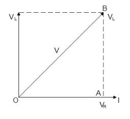
From the figure, we get in the right-angled triangle $OAB$
${V_R} = {I_R}$ and ${V_L} = I{X_L}$ where ${X_L} = 2\pi fl$
Now $V = \sqrt {{{\left( {{V_R}} \right)}^2} + {{\left( {{V_L}} \right)}^2}} $
$ \Rightarrow {V_R} = \sqrt {{V^2} - {V_L}^2} $
Substituting the given values we get
$ \Rightarrow {V_R} = \sqrt {{{220}^2} - {{176}^2}} $
$ \therefore {V_R} = 132{\text{ V}}$
Hence option A is the correct answer.
Additional information: Phasor diagrams are diagrams representing alternating current and voltage as vectors with the phase difference between them. Phasors are rotating vectors but they represent scalar quantities. Thus a sinusoidal alternating current and voltage can be represented by rotating vectors. The length of the vector is equal to the peak value of alternating voltage or current.
In purely inductive circuits when current reaches its maximum value after voltage becomes maximum then-current lags behind the voltage. And in a purely inductive circuit, when current reaches its maximum value before the voltage reaches its maximum then-current leads ahead voltage. And in purely resistive circuits, the current and voltage are in the same phase when they reach their maximum value.
Note: The circuit that is given to us is an LR circuit that means it contains only an inductor and a resistor and thus the current lags behind voltage so we need to be careful while drawing the phasor diagram for the circuit. And since we are treating the current and voltage as vectors so we use the vector property of shifting and we apply the Pythagoras theorem to the triangle formed.
Complete step by step answer:
We will draw a phasor diagram for a resistor-inductor to calculate the voltage through the resistor. We will take current as the reference and will draw the voltage drop across the resistance in phase with the current. And we will draw the voltage across the inductor ahead of the current with a phase difference of $90^\circ $ because of current lag voltage in a purely inductive circuit. The vector sum of two voltage drops will be equal to the applied voltage.
From the figure, we get in the right-angled triangle $OAB$
${V_R} = {I_R}$ and ${V_L} = I{X_L}$ where ${X_L} = 2\pi fl$
Now $V = \sqrt {{{\left( {{V_R}} \right)}^2} + {{\left( {{V_L}} \right)}^2}} $
$ \Rightarrow {V_R} = \sqrt {{V^2} - {V_L}^2} $
Substituting the given values we get
$ \Rightarrow {V_R} = \sqrt {{{220}^2} - {{176}^2}} $
$ \therefore {V_R} = 132{\text{ V}}$
Hence option A is the correct answer.
Additional information: Phasor diagrams are diagrams representing alternating current and voltage as vectors with the phase difference between them. Phasors are rotating vectors but they represent scalar quantities. Thus a sinusoidal alternating current and voltage can be represented by rotating vectors. The length of the vector is equal to the peak value of alternating voltage or current.
In purely inductive circuits when current reaches its maximum value after voltage becomes maximum then-current lags behind the voltage. And in a purely inductive circuit, when current reaches its maximum value before the voltage reaches its maximum then-current leads ahead voltage. And in purely resistive circuits, the current and voltage are in the same phase when they reach their maximum value.
Note: The circuit that is given to us is an LR circuit that means it contains only an inductor and a resistor and thus the current lags behind voltage so we need to be careful while drawing the phasor diagram for the circuit. And since we are treating the current and voltage as vectors so we use the vector property of shifting and we apply the Pythagoras theorem to the triangle formed.
Recently Updated Pages
Master Class 12 Business Studies: Engaging Questions & Answers for Success
Master Class 12 Biology: Engaging Questions & Answers for Success
Master Class 12 Chemistry: Engaging Questions & Answers for Success
Class 12 Question and Answer - Your Ultimate Solutions Guide
Master Class 11 Social Science: Engaging Questions & Answers for Success
Master Class 11 English: Engaging Questions & Answers for Success
Trending doubts
Which are the Top 10 Largest Countries of the World?
Draw a labelled sketch of the human eye class 12 physics CBSE
Differentiate between homogeneous and heterogeneous class 12 chemistry CBSE
Sulphuric acid is known as the king of acids State class 12 chemistry CBSE
Why is the cell called the structural and functional class 12 biology CBSE
Which is the correct genotypic ratio of mendel dihybrid class 12 biology CBSE